Thursday, January 16, 2014

Homebrewed Off-Center Fed Dipole


Ocfd.jpg
Building A Homebrewed Off-Center Fed Dipole Scanner Antenna.

Aluminum/copper tubing construction:

You will need to check the fit of the tubing with the T connector and the caps while you are at the store. One combination that fits nicely is 3/4" copper pipe with 3/4" CPVC fittings (not to be confused with 3/4" PVC fittings which will be too large). The tubing/connector is held in place with 2 stainless steel sheet metal screws for connecting the balun to each element.
Find a "U" bolt to fit your mast. Drill two holes in the support pipe to fit the U bolt.The support pipe is 18" from the "T" to the mast.

Remember, bandwidth increases as diameter of the elements increases. I think, if I remember correctly, at the hardware store, that a few CPVC fittings will fit copper tubing perfectly!

Some say that the 18" element on top mounted works best,Some like the 48" element on top.It does'nt matter,it works the same. If you use the copper tubing,be sure to paint it with some good,non-conductive paint.I used to paint mine light grey. -Have fun! (Teraycoda)

For an alternate/temporary mounting option, drill a hole in one of the end caps and put in an eye bolt with a nut on the underside of the cap to secure. Be sure to secure this end cap to the copper tubing somehow, perhaps with an additional small stainless sheet metal screw. Be sure that the eye bolt itself doesn't make electrical contact with the tubing. Also, drill a small weep hole in the bottom end cap to allow any moisture to escape that may accumulate inside. Use the eye bolt and some rope to pulley the antenna up high in a tree, or use a hook to hang it somewhere. Give careful consideration to safety and grounding depending on your particular usage scenario. (Qdude)

Variation for Off-Center Fed Dipole Using Simple Wire and 75 to 300 ohm TV Balun Transformer

Offset dipole scanner antenna.jpg
Electrically, this version is the same as the one using copper tubing (above) but can be assembled quickly and is quite portable. While not as broadbanded as an OCFD using copper tubing or other metal with a larger diameter, the OCFD made from simple wire turns in great receive performance in all the commonly scanned bands, as reported here on RR in multiple message threads.
 
The legs/ends of the dipole are simple bell wire and shown here coiled up. Uncoil them and hang them vertically; doesn't matter if the long or short leg is at the top... works the same either way. The wire terminal lugs shown at the end of the legs of the dipole antenna should NOT be connected electrically to the wires - just crimp them on over the wire insulation. They are used as convenient hangers for the antenna, and not meant for electrical connection. Obviously, the lugs at the TV transformer/balun ends of the wire should be stripped before crimping on the terminal lugs to ensure contact with the antenna wires when you attach the TV transformer. Ensure the 75 ohm coax feedline that you connect from the balun/transformer runs away from the antenna at as near a 90 degree angle as possible.

Sunday, December 29, 2013

H antenna


It is known that a single dipole antenna tuned neslishkom has a high gain. But if you use two of these antennas connected a phased power line, then we can increase the gain of the antenna. The result is an antenna system comprising two types of dipole antennas, is reminiscent of the Latin letter h and with the name of "lying h". This antenna (lying h) feeding points has high input impedance and it soglosovat to the power supply line of arbitrary length requires use quarter wave transformer. Antenna type "bream h" has exactly takuyuzhe radiation pattern in the horizontal plane as the normal dipole antenna. But the radiation pattern in the vertical plane in the investigation narrows the location of two dipoles of each other and that this expense and get a win to be reinforced. But this antenna system has its drawbacks - namely, suspension height. Necessary to lower the dipole antenna "lying h" was at the height of not less than L / 2 + height of the top of the dipole. The approximate gain of the antenna "lying h" 5-6 dB! And it is much more than a single dipole. The figure shows the dimensions of the antenna "lying h" for three ranges of 14, 21, 28 MHz. As the supply line used by the resonant power line, it Is located horizontally to a measure on the longer L / 2. For this it is necessary to use another mast. Radiation pattern is the range of frequencies used.

Vertical delta-loop antenna


This month I would like to share an idea from my sketchpad with you. I am planning to build a vertical delta-loop antenna for 20 meters. The reasons for choosing this design:
  • My favourite HF band is 20m
  • Delta-loops for 20m are manageable in size
  • Loops are quiet on receive
  • Vertically polarized loops are well suited for DX
I found the delta-loop overview below at the website of W5SDC:

Delta-loop overview.

My choise of shape will be version D because if offers a low radiation angle, which is necessary for DX. The sketch below shows how I plan to build the antenna:

Delta-loop antenna for 20m.

A delta-loop antenna with ATU was described by WB8IMY and published in QST May 2002: One Stealthy Delta. This article is worth studying if you consider constructing a loop antenna.

OZ1BXM Lars Petersen

Building a 2m quarter-wave ground-plane antenna


The first antenna that you should consider building is the quarter-wave ground-plane antenna for the 2m band. They are very easy to build and will perform better than the antennas that come with most handhelds.

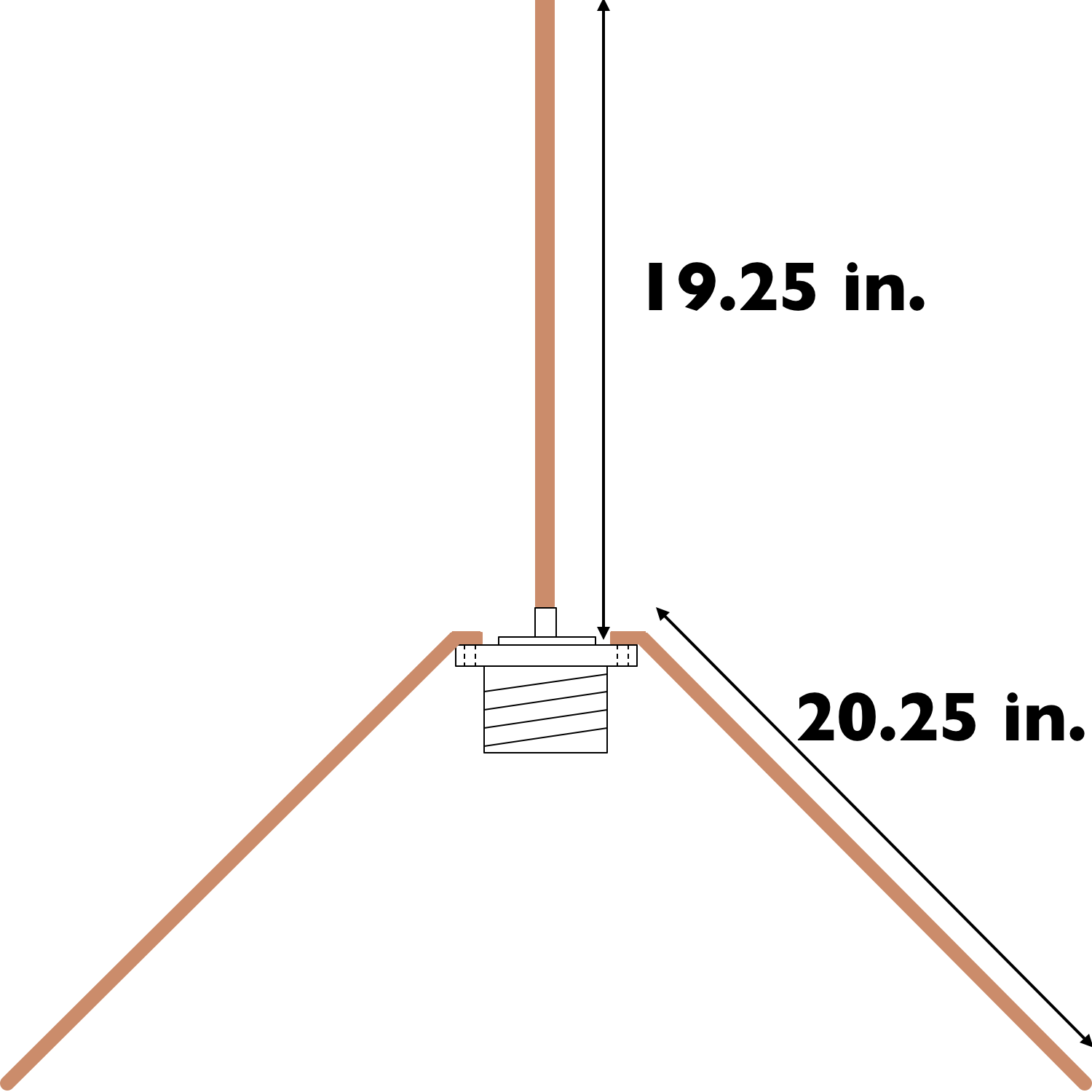
The quarter-wavelength, ground plane antenna is made up of one vertical element, called the driven element, and four radials. The radials make up the ground plane. An easy way to make this antenna is to use an SO-239 coax connector. The driven element is soldered directly to the center conductor, while the four radials are connected to the four holes in the connector’s flange. See the figure at right.
2m ground plane antenna
A simple 2m antenna can be made with an SO-239 connector and four short pieces of stiff wire.
 
Now, let’s calculate how long the elements should be. Since the wavelength of a radio wave is equal to 300/f (MHz), one quarter wavelength will be equal to 75/f (MHz). At 146 MHz, therefore, the length of the driven element is:
75/146 = .51 m

In practice, we have to make one more adjustment. Because a radio wave travels more slowly in a wire than it does in free space, the wavelength will actually be about 5% less in a wire than in free space. So, we multiply the wavelength in free space by .95 to get the length of the driven element:

.51m x .95 = .49m = 19.25 inches

The radials should be about 5% longer than the driven element. This isn’t really very critical, so if you make them 20.25 inches long, the antenna will work just fine.

You should make the elements out of a stiff wire. 12 AWG copper wire will work for experimentation purposes. Welding rod might be better for a more permanent antenna.
You need to solder the 19.25-in. driven element to the solder cup of the center conductor of the SO-239 connector. Attach the radials to the holes in the flange of the SO-239 connector with nuts and bolts. You can also use these nuts and bolts to mount the antenna to some kind of bracket. Bend the radials out to a 45-degree angle, connect a coax cable to it, and start having fun