Magnetic Loop Diagram
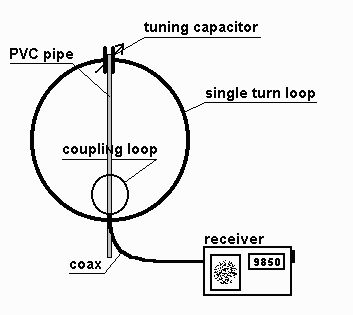
Magnetic Loop antenna

This antenna has several advantages, not least being only 1 metre diameter! This loop relies on being horizontally polarised and receives only the magnetic wave, thus as most noise in the domestic environment is vertically polarised and electrical wave, it delivers low noise to your transeiver/receiver, which makes for nice clean listening. In addition any signal arriving in the direction of the loop end on will be nulled out, this can be useful to get rid of an interfering signal by simply rotating the loop leaving the desired signal in the clear. It can be used indoors with ease and works well at ground level which is not the case for long wire/dipole antennas at shortwave wavelengths.
So what are its disadvantages? Well its tuning is critical, such that for a small change in frequency the antenna will need to be retuned at the loop end. This is even more important for transmitting where a high reflected wave (swr) due to not being tuned correctly will damage the output stage of your transmitter! In addition due to the very high "Q" of the loop, very high voltages can build up on the loop tuning capacitor even with low amounts of power from your transmitter. It is for this reason I recommend this loop is used with a transmitter of no more than 8 watts, any more and the ordinary broadcast tuning cap will arc over with spectacular results. Of course should you wish, a higher spec/bigger air spaced tuning cap would allow higher power output transmitters to be used. Also I consider the use of remote tuning using a fairly high geared motor and insulated coupling on the tuning cap essential. For shortwave listeners manual tuning would suffice.
In setting up the tuning of the loop, connect to a receiver and tune to 14 mhz. Now tune the loop which as it nears peak tuning will cause a whooshing sound. Stop the tuning you should now hear good strength signals in your receiver. For tuning for a transmitter, 1st use receive method then apply low power and fine tune loop tuning and tweak gamma match for lowest swr.
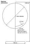
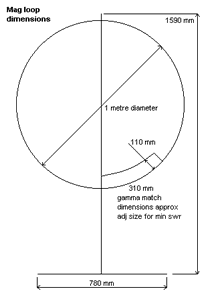
Magnetic loop dimension details
- Diameter of loop 1000mm
- Diameter of tube 15mm
- Width of base 780mm
- Diameter of support pipe 42mm
- Loop end spacing (for tuner) 50mm
- Height of support 1590mm
- Nylon board 210x240mm
- Nylon board 240x70mm
- Gamma match width 310mm
- Gamma/loop spacing 110mm
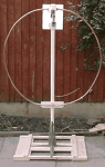
Construction Tips
- Use a bicycle wheel with no tyre on to help form the curves of the soft annealed copper tube
- Clean the tube with wire wool before any soldering
- Use a 100 watt soldering gun for the joints, but use a small blow torch first to get the copper at temperature to take a joint
- Force some timber with the corners planed off down the plastic plumbing pipe this will stiffen the pipe as the loop is quite weighty
- Use inverted shelf brackets to support the mounting pipe and make a wooden frame wide enough to hold up the loop