Tuesday, June 24, 2014

Putting up a Long-Wire Antenna


Fig. 2 Longwire antenna

Fig. 2 Longwire antenna


I've actually used this kind of antenna. When I was a teenager, I used it with my old Realistic stereo receiver to improve its AM reception, and it did work. (My dad put it up for me.)

Note: RadioShack sells this antenna as a kit, catalog # 278-758, $9.99 in their 2000 Catalog. You might also find it from other electronics suppliers. They sell the antenna wire as catalog # 278-1329, $6.99 in the same catalog. The insulators can be ordered for shipment to your house through RadioShack RSU catalog # 12099248, $4.79 + shipping in the 2000 Catalog.

Find two points, such as two poles (NOT utility poles!), or as most people will do, the corner of your house and a tree. Any safe places above the ground from which you can string this wire will do. Remember that not just the mounting places, but the "air-space" through which the wire will be strung must be free of obstructions, such as trees, and especially power lines. Whatever you do, don't put it on the same corner of the house through which your electrical service enters! First, that will be dangerous, and second, you'll pick up power line noise.

This antenna picks up signals best at right angles. It picks up worst end-on. Therefore, remember to orient the wire to pick up from the direction in which you are most interested.

Using an eye-hook at each point, attach a length of nylon rope. Tie the other end of the nylon rope to each insulator. The bare copper wire is strung from between the insulators, as shown in the diagram.

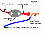
Use an insulated wire to connect to the copper wire at the end closest to your radio. Strip a couple inches of it and wrap it around the bare copper wire. For best results, solder this connection. This is shown in Figure 2. 

If you string the wire from a stationary point (such as a house) to a tree, use this trick that my father taught me, and that Ham Radio operators use. You see, the tree will sway in the breeze, stretching the wire over and over, eventually breaking it. So on the tree, instead of using a plain eye-hook, put up a pully (such as a clothsline pully). Run the nylon rope through this pully, letting a few feet hang down, and tie a brick (or suitable heavy weight) to the end of the rope. This is what I have illustrated in the first diagram. As the tree sways in the breeze, the rope moves feely through the pully, and the weight of the brick keeps the whole thing taut.

Grounding: From the ground terminal on your radio (next to the antenna terminal) run a wire to either a copper cold-water pipe (PVC pipe won't work) or a copper ground rod driven into the ground.

Some safety notes:

1. Keep your antenna far away from power lines! If you, your antenna or your ladder touches a power line, you could be KILLED.

2. Remember that you will be climbing ladders or trees to high place. Observe every safety precaution. Never extend the ladder beyond the manufacturer's reccomendation. Never stretch to reach a point-- instead, move the ladder. Have the ladder on a secure footing, and have someone there to hold the ladder.

3. Make sure your antenna is in a safe place, high enough so people or pets won't walk into it by accident. (Plus, the higher up you get it, the better it works).

4. Use lightening protection! Make provisions to disconnect and ground the antenna when not in use. C. Crane Company and RadioShack offer lightening protection devices. However, disconnecting and grounding the antenna is still the best option. RadioShack sells a simple knife switch you can use for this. Screw it to the wall or table next to the radio, hook one side to the antanna, the other to a wire leading to a copper grounding rod, or the copper cold-water pipe leading outside of your house. (Remember this doesn't work if you forget to throw the switch!)

Long Loopstick Antenna


Wound on a 3 foot length of PVC pipe, the long loopstick antenna was an experiment to try to improve AM radio reception without using a long wire or ground. It works fairly well and greatly improved reception of a weak station 130 miles away. A longer rod antenna will probably work better if space allows. The number of turns of wire needed for the loopstick can be worked out from the single layer, air core inductance formula:
Inductance = (radius^2 * turns^2) / ((9*radius)+(10*length))

where dimensions are in inches and inductance is in microhenrys. The inductance should be about 230 microhenrys to operate with a standard AM radio tuning capacitor (33-330 pF). The 3 foot PVC pipe is wound with approximately 500 evenly spaced turns of #24 copper wire which forms an inductor of about 170 microhenrys, but I ended up with a little more (213uH) because the winding spacing wasn't exactly even. A secondary coil of about 50 turns is wound along the length of the pipe on top of the primary and then connected to 4 turns of wire wound directly around the radio. The windings around the radio are orientated so that the radio's internal antenna rod passes through the external windings. A better method of coupling would be to wind a few turns directly around the internal rod antenna inside the radio itself, but you would have to open the radio to do that. In operation, the antenna should be horizontal to the ground and at right angles to the direction of the radio station of interest. Tune the radio to a weak station so you can hear a definite amount of noise, and then tune the antenna capacitor and rotate the antenna for the best response. The antenna should also be located away from lamp dimmers, computer monitors and other devices that cause electrical interference.

Magnetic loop antenna for 7-21 mhz

 
  • Magnetic Loop Diagram

    Magnetic Loop Diagram

  • Magnetic Loop antenna

    Magnetic Loop antenna

This antenna has several advantages, not least being only 1 metre diameter! This loop relies on being horizontally polarised and receives only the magnetic wave, thus as most noise in the domestic environment is vertically polarised and electrical wave, it delivers low noise to your transeiver/receiver, which makes for nice clean listening. In addition any signal arriving in the direction of the loop end on will be nulled out, this can be useful to get rid of an interfering signal by simply rotating the loop leaving the desired signal in the clear. It can be used indoors with ease and works well at ground level which is not the case for long wire/dipole antennas at shortwave wavelengths.

So what are its disadvantages? Well its tuning is critical, such that for a small change in frequency the antenna will need to be retuned at the loop end. This is even more important for transmitting where a high reflected wave (swr) due to not being tuned correctly will damage the output stage of your transmitter! In addition due to the very high "Q" of the loop, very high voltages can build up on the loop tuning capacitor even with low amounts of power from your transmitter. It is for this reason I recommend this loop is used with a transmitter of no more than 8 watts, any more and the ordinary broadcast tuning cap will arc over with spectacular results. Of course should you wish, a higher spec/bigger air spaced tuning cap would allow higher power output transmitters to be used. Also I consider the use of remote tuning using a fairly high geared motor and insulated coupling on the tuning cap essential. For shortwave listeners manual tuning would suffice.

In setting up the tuning of the loop, connect to a receiver and tune to 14 mhz. Now tune the loop which as it nears peak tuning will cause a whooshing sound. Stop the tuning you should now hear good strength signals in your receiver. For tuning for a transmitter, 1st use receive method then apply low power and fine tune loop tuning and tweak gamma match for lowest swr.

Magnetic loop dimension details

  • Diameter of loop 1000mm
  • Diameter of tube 15mm
  • Width of base 780mm
  • Diameter of support pipe 42mm
  • Loop end spacing (for tuner) 50mm
  • Height of support 1590mm
  • Nylon board 210x240mm
  • Nylon board 240x70mm
  • Gamma match width 310mm
  • Gamma/loop spacing 110mm

Construction Tips

  • Use a bicycle wheel with no tyre on to help form the curves of the soft annealed copper tube
  • Clean the tube with wire wool before any soldering
  • Use a 100 watt soldering gun for the joints, but use a small blow torch first to get the copper at temperature to take a joint
  • Force some timber with the corners planed off down the plastic plumbing pipe this will stiffen the pipe as the loop is quite weighty
  • Use inverted shelf brackets to support the mounting pipe and make a wooden frame wide enough to hold up the loop