Many RASON members truly enjoyed last month's collinear antenna. This month I decided to build a 2 meter 5/4 wave antenna. This antenna is unique in that it is enclosed entirely in 3/4" PVC which makes the design a little more complicated. The primary problem is that PVC tubing has a significant velocity factor which causes RF to slow down. This means that an antenna encased in PVC will normally need to have it's physical length reduced by about 19%. To further complicate the design, a 5/4 wave antenna's impedance has a highly inductive component which must be tuned out to get a good match. Fortunately, the design in Figure 1 solves all of these problems.
Tuesday, June 17, 2014
Oz Report's Antenna
2m (144-148 mHz) Antenna with molded BNC connectors (the only kind worth anything in hang gliding harnesses).


Five foot long total RG58C/U coaxial cable. 19.5" of unshielded center cable (for 144-148 meters) which you attach to your harness mains (using tape).
The ground wire is the exposed shielding wire, the mesh wire that normally surrounds the interior wire. This is how you hook it up in your harness: http://sahga.com/harness_antenna_2.gif.

You can just tape down the braid also.
I have also had adequate success just cutting off the braid exposed ground line like this:

Click on above to view a higher resolution image.
Connect the antenna, as shown in the diagram above, to your mains. I suggest in a manner to protect the junction at the end of the shielding from flexing, so run the shielding up the mains for a couple of inches, if you have the room.
I have normally cut off the ground as it is sometimes a bit of a hassle to place horizontally along the back plate, but by leaving it on you have better matching of your antenna to your radio to get the highest signal power output. I've had good luck even with the ground gone.
The antenna is cut to 19.5 inches which corresponds to 144 mhz. You can cut the antenna a bit shorter for high frequencies if you like, although the differences are quite small. To know how long to cut the antenna (the single center strand), it is length (in inches) = 2808/freq in mHz. For example, for 147 mHz, length equals = 2808/147 = 19.1 inches.
Single 5/8 Flower Pot Antenna
The Single 5/8 version of the Flower Pot simply substitutes a 5/8 wave-length section for the top quarter wave of the basic half wave antenna design. The arrangement is shown in the sketch below. The 5/8λ radiator uses a 0.2λ (shorted) co-ax phasing stub to resonate the 5/8λ element. In a conventional 5/8λ mobile whip, an inductor is used to bring the 5/8λ element to resonance; however, in this Flower Pot style of antenna, using a co-ax phasing (or delay) stub suits the construction technique and has the advantage of being able to be precisely determined and cut at the construction stage.
The antenna configuration is similar to, but slightly shorter than, the “Gain Sleeve” antenna described in the RSGB Hand-book (6th Edition – figure 13.99, which itself is derived from the reactance – or shunt – fed 5/8λ monopole antenna at figure 13.84 of the handbook).
The Gain Sleeve antenna achieves an effective radiating element length of one wavelength and, since the aperture is twice that of a half wave dipole, a theoretical gain of 3dBd (gain over a dipole) could be achieved.
However, note that the Handbook indicates that in practice, the Gain Sleeve antenna would realise about 2.5dBd. The effective radiating element length of the Single 5/8 Flower Pot is 7/8λ suggesting it would have somewhat less than 2.5dBd gain.
2m Construction

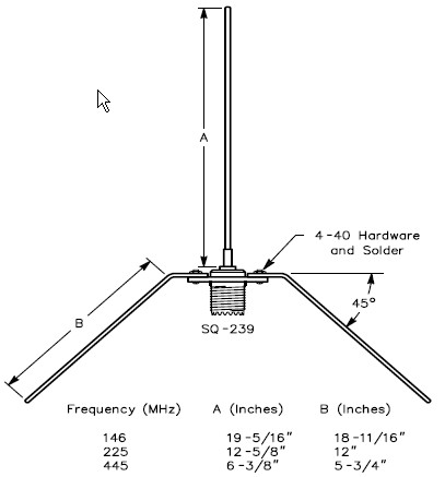
Simple 1/4 Wave Ground Plane Antenna

If you are just starting out or have the desire to build an antenna here is a simple and fun project. This antenna is perfect for those hams living in the primary coverage area of the .075 repeater. The radials can be made of no. 12 copper wire. The vertical radial (A) should be soldered to the center connector of the SO239. The four base radials (B & C) and (D & E) can be soldered or bolted to the SO239 mounting holes using 4-40 hardware. The four base radials then should be bend downward to a 45 degree angle. The antenna can be mounted by clamping the PL259 to a mast or even passing the coax through a 3/4 ID PVC pipe and compression clamping the PL259. Either way let your creativity flow. If you plan on mounting it outside experience teaches to apply RTV or sealant around the center pin to keep water out of the coax.
Make each radial a 1/4 wave of your desired frequency. Sometimes it helps to add a little extra length to the radials. This will give you some snipping room when you adjust the SWR.
example calculation:
Freq (mhz) A (inches) B&C/D&E (inches)
146 mhz 19-5/16 20-3/16
example calculation:
Freq (mhz) A (inches) B&C/D&E (inches)
146 mhz 19-5/16 20-3/16
VHF/UHF Ground Plane antennas for under $20
|
Subscribe to:
Posts (Atom)