Wednesday, February 16, 2011

A J-pole aerial for 50MHz

image

Figure   shows the aerial in its diagrammatic form. Notice that the aerial is in the form of an elongated letter ‘J’; this shape gives rise to its nickname – the J-pole. The quarter-wave
RF transformer is the lower ‘U’ section below the half-wave element. At the bottom of the U section, the impedance is zero (this may become clearer later) and at the top of the U section it is high, thus matching the aerial impedance. The coaxial feeder cable is connected part-way up the U section, where the impedance is around 50 .


image

A vertical aerial for 70 cm

image

The aerial element and the coil are made from a single piece of 1.5mm welding (brazing) rod, and the dimensions are given in Figure . Wind the coil around a 4mm rod or the shank of a twist drill. The lower end is filed to a point and then soldered into the centre conductor of a 4-hole panel- mounting BNC socket. (Try to obtain a good-quality BNC socket with
PTFE insulation – the insulation of cheaper sockets is easily damaged.) Trim the element to 427mm (top of element to top of coil) after the wire has been soldered to the socket.
The base coil causes the aerial to be rather  ‘whippy’, so a piece of 5mm plastic knitting needle can be cut to the length of the coil and then forced into it. The radials are made from four lengths of 3mm welding rod. These are bent and soldered into the four mounting holes of the socket, and then cut to the lengths shown in Figure .

The aerial is made waterproof by enclosing it in a 22mm diameter PVC waste water pipe. It is  ‘weldable’, and available at plumbers’ merchants, usually by the metre. A coupler is slotted to take the radials (Figure ). Filethe BNC socket as required, so that it slides inside the coupler until the radials poke out of the slots. Cut a length of plastic tubing which is 30mm longer than the aerial, and push it into the coupler. You will then need a plastic bung or screw-top to waterproof the top end.

Two & Six Meter Beam antenna


4EB146

Four element, two meter beam, elements can be tubular aluminum, solid aluminum, or for low terrestrial noise, use fiberglass elements.  This beam may be installed vertical, or horizontal.For optimum performance and gain, feed with BUX COMM  "VBALUN."


4EB54
Four element, six meter beam, elements can be tubular aluminum, solid aluminum, or for less terrestrial noise, use fiberglass elements.  This beam may be installed vertical, or horizontal.

2M J Pole antenna

2jpole

6 M Base station Di-pole antenna

6mdipole
tennas & Accessories

A Two-Band Fan Dipole


A two-band dipole can be constructed by connecting together the feed point two dipoles for even harmonically related bands. It is fed with 50-ohm coax with or without a balun. The best example of this is 80 and 40-meter dipoles connected together. Both dipoles are cut for half-wave resonance on each of the two bands. They are fed together and the ends of the wires are spread apart. If the ends are close together, there will be interaction between the dipoles. In such an antenna system, both dipoles must be carefully pruned for lowest SWR one band at a time. The lower band will be tuned first since the shorter dipole will not interact with the longer one. Each dipole has a low antenna resistance on the band for which it is resonant. RF energy follows the path of least resistance, and it automatically selects which dipole will receive power. The remaining antenna will have a high impedance. High impedance will block RF. Such an antenna will have a narrower bandwidth than a single band dipole, but close to the resonant frequency of each dipole, a tuner will not be needed. To connect many dipoles for multiple bands is possible, but it is not recommended because multiple wires are prone to interact and it will be impossible to achieve a low SWR on some bands. However, on the two band model, the 40-meter dipole will resonate close to 15 meters, the 80-meter dipole will resonate close to 10 meters, and working four bands with this set-up is possible. Some hams are using this antenna successfully with a tuner on all bands, although the signal on 20 meters suffers somewhat because of high SWR.

Figure - Two-Band Fan Dipole for 40 and 75 Meters

2bandfandipole4075

The Double Bazooka Dipole


image

The double bazooka is claimed by its users to be broad-banded, a quality especially interesting for those hams operating on 75/80 meters. Tests done at the A.R.R.L. have shown the double bazooka is only slightly more broad-banded than a regular dipole, probably due to the use of a large conductor (coax) for the center part of the antenna. The double bazooka will not transmit its second harmonic, and its users say it does not need a balun. Other users say it is quieter than a regular dipole.

The center of the antenna is made from RG-58 coax. To find the length of coax needed, divide 325 by the frequency in MHz. The coax forms the center part of the double bazooka and a piece of number 12 wire on each end completes the antenna. The length of each of the end wires is found by dividing 67.5 by the frequency in MHz. To increase the bandwidth some builders use shorted ladder-line in place of the number 12 wire, which makes the end pieces to be electrically larger.

The feed-point of the double bazooka is unique. At the center of the coax dipole, remove about 3 inches of the plastic covering, exposing the shield. Cut the shield in the center and separate it into two parts. Do not cut the dielectric or the center conductor. Leave the center conductor with its insulation exposed. On the feed-line strip off about 3 inches of outer insulation, separate the shield from the center conductor, and strip about 1 inches of the insulation from the center conductor. To attach the feed-line, solder the two exposed feed-line conductors to the two pieces of the separated exposed shield of the dipole center. It goes without saying: seal the feed-point to prevent water from getting in. At each of the two ends of the coax forming the center of the antenna, the coax is stripped back and the center conductor and shield are shorted together and soldered. The end wires are soldered to the shorted coax ends, run to insulators at the end of the antenna, and the soldered joints are sealed against the weather.

New Carolina Windom Antenna

windom_K4IWL
Windom design for 40m 20m 15m and 10m by K4IWL
http://www.hamuniverse.com/k4iwlnewwindom.html

A simple 6m beam


image

The beam is shown in Figure . The driven element is the one whose centre is fed by the coaxial cable, and lies between the two insulators marked A and the feedpoint at B. The reflector is also anchored at the points A, and lies over the upper half of the frame.


image

The wooden centrepiece is used to support the cross-pieces and to mount the aerial on the mast, using a common shelf bracket. The cross-pieces, known as spreaders, can be wooden canes or dowelling, and are mounted to the centrepiece using cable clips and adhesive. Figure  shows how this is done.

If the aerial is to be a permanent installation, the spreaders should be weatherproofed using a good-quality exterior varnish. The wire elements are PVC covered and fed through holes in the spreaders

3 ELEMENT YAGI BEAM 50 MHZ(6M)


The diagram and photograph above show an inexpensive compact 3 element beam for 6m. The aluminum pole I used for the boom was obtained from a local shop. The aluminum tubing used for the elements and element to boom mounting clamps came from DEE COMM (suppliers of antenna hard wear for home constructors)

As you can see from the diagram the antenna has a gamma match. It is easy to construct. The capacitor is a length of heavy duty coax with the outer braid stripped off. The insulated inner and wire is inserted into the gamma bar tube. By adjusting the length of the bar sliding the coax inner up or down the tube the capacitance can be changed over a wide range. The coax from the shack is fed to the SO239 connector on the plastic weather proof box.

Because of the gamma match the driven element does not need to be cut in the centre, this makes the antenna stronger and is known in the old days as the plumbers delight.

The antenna has a forward gain of about 6-7dBd. It does not look out of place when on the mast. It could even be installed in the attic as the turning radius is quite small.

http://www.gameangler.eu/delboy/m0dad/Homebrew/3_element_beam__50_mhz.htm

WIRE DIPOLE ANTENNAS


The dipole is one of the most important and popular antennas, it forms the basis of many other different types of aerial which are directional and have gain in certain directions.

The dipole in its basic form consists of two identical lengths of wire with the feeder connected in the middle as in the diagram above. It can be any number of electrical wavelengths long. The most popular is the half wave dipole, normally thought of as a single band aerial.  Although it has little gain, it can be easy and cheap to construct, and they often prove to be the ideal solution with amateur radio operators who are only interested in one particular band .

HORIZONTAL

SLOPER

The wire dipole is normally mounted horizontal, vertical or sloping between two supports, but it can be erected in many different shapes such as the inverted-V or a Z shape. On the lower HF bands the the lengths become rather long so it is sometimes necessary to bend the antenna to fit the average garden.

INVERTED-V

The formula to calculate a half-wave dipole (in feet) on any HF frequency is 468/frequency in MHz. This is total wire length tip to tip, or 234/frequency in MHz for each element length. For example = If you want the antenna for 40 meters, choose the centre part of the band or centre part of the frequencies you want to work, 468/7.05 MHZ = 66.3 feet. It is better to make the wire slightly longer and then trim the wire to resonance. Make sure you trim the same length of each end.

In free space the feed point impedance is 78W so it is a good match to 75W coax. However when erected in the garden or over the house the impedance changes and it is acceptable to use 50W coax cable.

Although it is not essential, it is best to use a 1:1balun. This is connected between the two elements and the feeder cable. This ensures the correct operation of the antenna. It does not provide any impedance match, but it will balance the load by causing equal but opposite phase currents to flow in the conductors reducing radiation on the transmission line

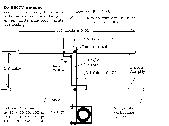
VHF Beam


HB9CV VHF Beam Antenna

navAID Figure 980 : Hb9cv VHF Beam Antenna

VK2ABQ BEAM 50 MHZ (6M)


The VK2ABQ is an easy beam antenna to build. I built one for portable use for the 6m band, you can see the details in the above diagram. The antenna is a two element yagi made with wire and the element legs bent back to reduce the size. This also makes it a popular antenna for 28,21 and 14MHz.

The support arms can be made of a none conductive material such as PVC or fibre glass tubing, or for a temporary antenna you could use dowel or bamboo canes, drill a small hole through each arm to thread the wires. Attach the cross arms to the centre plate with small u-clamps. The centre plate is a piece of plywood 6 inches square. The centre insulators can be made of Perspex, or any other lightweight none conductive material.

The beam is fixed to the mast with L-brackets available at any handyman shop. Make sure the beam is mounted horizontal as most operators use horizontal polarization on 6m SSB. 

For final adjustments, connect an S.W.R. meter between your transceiver and antenna and trim the driven element wire. Cut the same amount off each side of the wire until you have achieved a good S.W.R. for the part of the band you wish to work on.

The transmitted power will radiate in the opposite direction of the reflector, for example if you look at the antenna in the diagram, the radiated power will go from the bottom to the top of the page.

The VK2ABQ is a great antenna to build, it works well on 6m and is a fraction of the cost of a commercial antenna.

Two & Six Meter Beam Construction


Four element, two meter beam, elements can be tubular aluminum, solid aluminum,
or for low terrestrial noise, use fiberglass elements.  This beam may be installed vertical, or horizontal. For optimum performance and gain, feed with BUX COMM  "VBALUN."

VHF/UHF X-Beam

image

This antenna design will typically have a 6-8dB gain and a forward to back ratio of 20dB

http://www.dbbear.com/k0emt/projant/xbeam/

W3EDP Antenna


image

The W3EDP needs a simple matching unit is needed to couple the wire to the rig and a counterpoise is required for some bands, however there is room for experimentation. It has been shown that different lengths or removal of the counterpoise altogether, can improve performance, as described in RadCom, August 1996 by G3LCK.

The Tuning capacitor in the AMU can be a 365 - 500pF broadcast type or a miniature version is OK for QRP use.

Counterpoise lengths: 3.5 & 7.0Mhz - 17ft ; 14Mhz - 6.5ft ; 28Mhz - none
Tuning Unit: Values for coils in the unit, based on a 2 inch former and 16 swg wire:
3.5Mhz 21 turns ; 7.0Mhz 7 turns ; 14.0Mhz - 5 turns.

Off Centre Fed Dipole (OCFD) - Windom Antenna

image

The "Windom Antenna" was described by Loren G. Windom W8GZ. It could be an ideal wire aerial for use in restricted spaces for multi-band operation. It may also be an good candidate for portable work.

It is a wire antenna, similar to a dipole, but unlike a dipole or doublet which is fed at the exact centre, a Windom or Off Centre Fed Dipole, as the name suggests, has the feed point off center. Current versions of the Windom have a balun at the feed point which is fed with coaxial cable. As with all aerials the aerial should be as high as possible. With the feed point at between 20 and 40 feet above ground the typical claimed impedance will be somewhere in the region of 200 Ohms so a 4:1 balun will typically be required. At greater heights, and depending upon the exact position of the feed point, the impedance may be higher and a 5:1 or 6:1 balun might be a better choice although balun losses will be greater.


The point at which a Windom is fed in the original design, which used an open wire to feed the aerial, was 15 percent off-centre. The current designs, which are fed with coaxial cable, are typically fed about 33 percent off centre, so one leg is 67 percent of the total length and the other leg is 33 percent of the overall length of the aerial.


The bands that are covered depends upon the overall length of the aerial:
11 metres long (approx) should cover 20m, 15m and 10m and the WARC bands with a tuner.
21 metres long (approx) should cover 40m, 20m, 15m and the 10m bands and WARC with a tuner.
41 metres long (approx) should cover 80m, 40m, 20m, 15m and 10m and WARC with a tuner.
80 metres long (approx) should cover 160m, 80m, 40m, 20m, 15m and 10m and WARC with a tuner.


Cut the aerial for the lowest band to be used. In imperial measurements using a familiar formula:

The longer leg will be 468 divided by the frequency and multiplied by .67 = length in feet
The shorter leg will be 468 divided by the frequency and multiplied by .33 = length in feet
According to which sources one refers, the formula can also be found as:
62.2% for one side and 37.8% for the other leg. So:
The longer leg will be 468 divided by the frequency and multiplied by .622 = length in feet
The shorter leg will be 468 divided by the frequency and multiplied by .378 = length in feet

End Fed Zepp Antenna


A popular antenna often used to save space is the End Fed Zepp. The End Fed Zepp gets its name from the fact that it was used as an end fed wire trailing out from the rear of Zeppelin airships. It consists of a 1/2 wavelength horizontal radiator wire connected to one conductor of a length of parallel 300 ohm or 450 ohm twin feeder, often quoted as being 1/4  wavelength long.

image
Zepp Antenna by K4EFW
http://www.hamuniverse.com/n4jaantennabook.html

K4EFW notes: "...A half-wave resonant antenna can be fed from its end. When fed this way, it is also known as an end-fed zepp. An end-fed zepp will work on its fundamental frequency and on odd and even harmonic frequencies. The end of a half-wave antenna has very high impedance, and an antenna fed this way is said to be voltage fed. Feeding a half-wave resonant dipole in the center means it is current fed. The normal way of feeding the end-fed antenna is with ladder-line. One side of the ladder-line is connected to one end of the antenna and the other side of the ladder-line is connected to nothing. To secure the unconnected side of the ladder-line, it is connected to a short wire running between two insulators.

Since the antenna is connected at its high impedance point, no current flows into an antenna, but there will be a large current in the center of this antenna. No current flows from the open side of the feed-line because it is at a zero current point.  The end-fed zepp can be matched by cutting the ladder-line to a quarter wavelength with the bottom end of the ladder-line shorted. A certain distance above the short is a 50-ohm feet-point and it can be fed directly with coax. You will have to find the 50-ohm point by trial and error. This method of feed makes it a single band antenna".

G7FEK Limited Space Multi-Band Antenna


image

image

The G7FEK design will allow operation on 80m / 40m / 30m / 17m / 15m / 12m with the possibility to add the 20m band.

Link Dipoles or Jumpered Dipoles

Link Dipoles  facilitate multi band operation by simply connecting the jumpers (one on each side of the aerial) to achieve the desired resonant band. Perhaps a bit bothersome for frequent band changes, but a very simple and effective aerial.

link_dipole_001

All Band Doublet Aerials


Check out the The All Band Doublet and the NorCal Doublet for very simple, effective and versatile antennas for multi band operation:

all_band_doublet_001


The all band doublet antenna is nothing more than a 1/2 wave dipole cut for your lowest operating frequency and fed with twin lead, ladder line, open wire, etc to a tuner that will accept a balanced line connection. IT IS NOT FED WITH COAX!
It can be designed for use from 160 through to 10 meters very easily using the standard 1/2 wave dipole formula:

468/freq MHz = total length (ft)
The exact length is not critical!

If there is insufficient room for a lower frequency version (160m or 80m), then the double can be designed to the shorter wavelength of the 40 metre band and used up to the 10 metre band. (Do not attempt to operate on a lower frequency than 7 MHz in that case since this could damage the a.t.u.)  It may be possible to connect the ends together and tune it against earth - if you have a good enough earth - and use lower frequency bands. For best results a doublet should be mounted as high as possible (as with many aerials) and can be erected as a flat top or inverted V.

For more see the dedicated page: The ALL Band HF Doublet on Ham Universe:  http://www.hamuniverse.com/hfdoublet.html

Coaxial Trapped Dipoles


A trapped dipole for 40m and 80m offers the advantage of being somewhat shorter than a full size single band 80m resonant dipole plus it offers 40m as a resonant band plus the possibility of working on 20m, 15m and 10m. There are several designs available on the web for this type of aerial so Google W3DZZ. One of the most comprehensive sets of instructions is by Len Paget G0ONX. Fine out more here:

http://www.users.icscotland.net/~len.paget/GM0ONX%20trap%20dipole.pdf

This would be my choice if I had the space, though since a dipole is a balanced aerial it would make more sense to use balanced twin feeder (as in the Spectrum Communications implementation of this design) rather than coaxial cable which is an un-balanced and more lossy feeder.

W3DZZ_002
The W3DZZ Trapped Dipole - a balanced aerial, so use balanced twin feeder!

Here is a variation on the W3DZZ antenna by the Maidstone Amateur Radio Society that adds a dedicated 10 meter (28MHz) resonant element as a 'fan'.

W3DZZ_001

W3DZZ Dipole Aerial design by the Maidstone Amateur Radio Society
http://www.btinternet.com/~shaun.scannell/club/w3dzz.htm

Fan Dipoles

A fan dipole is a very handy way of using a dipole that will be resonant on several bands - typically three or four. The fan dipole (a.k.a. Parallel Dipole)


See M0WYM's page for a QRP Fan Dipole design: http://www.radiowymsey.org/FanDipole/fandiploe.htm

See this page for construction details: http://www.hamuniverse.com/multidipole.html

fan_dipole_001

Inverted L Aerials


The Inverted L for 40m/80m is shown below. It is essentially one half of a W3DZZ dipole fed against ground using one 7.1 MHz trap. The 40m / 80m Inverted L has the advantage of providing both horizontal and vertical components. It's a very compact antenna and is simple to construct. It is most efficient, of course, on 80 metres and 40 metres, but can also be used, with an a.t.u., on 20m, 15m and 10m.  While Inverted L's might make good TX aerials, like ground mounted vertical aerials they can be quite noisy on RX.


Find out how to make one here:  http://www.users.icscotland.net/~len.paget/5%20band%20Inverted%20L.pdf

inverted_L_004
The basic layout of the Inverted L Antenna by Len Paget GM0ONX (Practical Wireless)

Adding 160m / Top Band to an Inverted L


The 160 metre Top Band can be added to this aerial by connecting a 3.5 MHz trap at the end of the 80 metre wire (where to monofilament joins the 6.55m section of wire below) with another length of wire on the other side, increasing the overall length of the antenna.
Find out how to do it here: http://www.users.icscotland.net/~len.paget/Inverted%20L%20adding%20top%20band.pdf

top_band_inverted_L_001

Adding Top Band to an Inverted L by Len Paget GM0ONX (Practical Wireless magazine)

Windom - Off Centre Fed Dipole


See some designs at these links:
http://users.erols.com/k3mt/windom/windom.htm
http://www.dxzone.com/cgi-bin/dir/jump2.cgi?ID=7478
http://www.radioelectronicschool.net/files/downloads/ocfdipole.pdf
http://www.hamuniverse.com/k4iwlnewwindom.html
http://www.g4nsj.co.uk/windom.shtml
http://www.m0ukd.com/Carolina_Windom/index.php

4

M0UKD -  4:1 balun. It is 17 bifilar turns on a half inch ferrite rod. 50Ω - 200Ω, 1-30MHz
http://www.m0ukd.com/Carolina_Windom/index.php
Line_Isolator_internal_m0ukd

M0UKD Line isolator - 10 turns RG8 on a half inch ferrite rod
http://www.m0ukd.com/Carolina_Windom/index.php
windom_K4IWL
Windom design for 40m 20m 15m and 10m by K4IWL
http://www.hamuniverse.com/k4iwlnewwindom.html

More information at BucksCom:   http://www.packetradio.com/windom.htm  or  http://www.buckscom.com/pdfzips/windom.pdf

The Double Bazooka Dipole

image

The double bazooka is claimed by its users to be broad-banded, a quality especially interesting for those hams operating on 75/80 meters. Tests done at the A.R.R.L. have shown the double bazooka is only slightly more broad-banded than a regular dipole, probably due to the use of a large conductor (coax) for the center part of the antenna. The double bazooka will not transmit its second harmonic, and its users say it does not need a balun. Other users say it is quieter than a regular dipole.

The center of the antenna is made from RG-58 coax. To find the length of coax needed, divide 325 by the frequency in MHz. The coax forms the center part of the double bazooka and a piece of number 12 wire on each end completes the antenna. The length of each of the end wires is found by dividing 67.5 by the frequency in MHz. To increase the bandwidth some builders use shorted ladder-line in place of the number 12 wire, which makes the end pieces to be electrically larger.

The feed-point of the double bazooka is unique. At the center of the coax dipole, remove about 3 inches of the plastic covering, exposing the shield. Cut the shield in the center and separate it into two parts. Do not cut the dielectric or the center conductor. Leave the center conductor with its insulation exposed. On the feed-line strip off about 3 inches of outer insulation, separate the shield from the center conductor, and strip about 1 inches of the insulation from the center conductor. To attach the feed-line, solder the two exposed feed-line conductors to the two pieces of the separated exposed shield of the dipole center. It goes without saying: seal the feed-point to prevent water from getting in. At each of the two ends of the coax forming the center of the antenna, the coax is stripped back and the center conductor and shield are shorted together and soldered. The end wires are soldered to the shorted coax ends, run to insulators at the end of the antenna, and the soldered joints are sealed against the weather.

End-Fed Random Length Antenna

image

Below is another end-fed antenna made from a random length of wire connected to the back of the tuner. The wire then exits the shack and goes to a high support where it then runs horizontally to another high support. The tuners groundside must be connected to a good RF ground, since a poor ground causes high losses. This antenna is commonly called a "long wire." Since the end of the antenna comes in the shack, you will be exposed to high levels of RF. In addition, this type of installation may cause RF to be picked up in the microphone, noted by distortion. The feed-point of the long wire being connected directly at the output of the tuner can have an impedance of a few ohms to a thousand ohms depending on the antennas length. If the wire is cut to a multiple of a half wave at the lowest frequency, the system will be efficient since it is fed at a voltage point and very little current flows into the ground. This antenna is really a variation of an inverted-L fed directly without a feed-line from the tuner.