Sunday, February 13, 2011

HF RDF Antenna


The Adcock HF RDF Antenna

The Adcock HF RDF Antenna

RDF Antenna - Combiner

RDF Antenna - Combiner

The Adcock antenna has been used for a long time for RDF. It is basically an interferometer.

When both of the two dipoles see exactly the same signal strength and RF phase, no signal is delivered to the receiver. This condition happens only when the signal source is equal distance from the two dipoles.

As the antenna is rotated through 360 degrees, there will be two directions where the signal will drop to a very low strength. This can be a very deep and narrow null. The direction readout is then read, and the direction of the signal is then known, with an ambiguity; we don't know which of the two null directions is the correct direction.
The directional ambiguity will be resolved when another station takes a bearing from some significant distance away. The two correct headings will cross, while the two incorrect ones will not cross.

Since this antenna only responds to vertically polarized components of signals, poor performance can occur when the signal is horizontal or nearly horizontal. Since purely horizontal signals are rare, it should function on most signals.

Construction

Construction is not critical. The only really important factors are electrical balance, and a lot of clearance distance to other objects. These factors may require the antenna be placed out in the open, away from the radio operating position.

The simplest arrangement would be a free-standing support with the vertical mast pivoted on a compass rose on the ground. This can be wood. Metal can be used for the support and for the cross-boom, as long as the two dipoles both always see the same capacitance from the structure. Symmetry is the name of the game here.

A remote speaker and remote S meter can be mounted at the antenna in a weatherproof box. The operator can tune in the suspect signal, and then go out to rotate the antenna and take the heading.

Detail of the Combiner circuit

The combiner circuit mounted on the cross boom is not critical for the antenna to DF. If a tiny toroid is used, use small diameter wire. If a large toroid is available, larger wire can be used. #30 wire would probably work for a 1/2 to 1 inch diameter toroid.The number of turns is not critical, but slightly greater sensitivity for weak signal

s may be achieved through experimentation.The feed line lengths on each side must be identical.The length of the dipoles is not at all important, so long as they are not resonant at some frequency of major interest. Phase characteristics of a resonant antenna are strongly affected by very slight detunings. If the two dipoles are not exactly the same (they won't be!) then the antenna will exhibit maximum error at the resonant frequency.

Because this is a broadband low-cost antenna, it is not possible to have good impedance match between the antenna and the feed line at all frequencies. Experimentation with turns ratio (bifiler turns versus coax feed turns) may provide an optimum match at some desired frequency, such as 20 meters. Mismatch on a receiving antenna is usually not important. Even with a poor antenna one can hear most of the signals on the band, because receivers today are so very sensitive.

A Magnetic Loop Antenna


Various articles have appeared describing magnetic loops for HF use, some with complicated methods of remote tuning and the antenna can be quite a useful and interesting project.

The article in Sprat 61 my Tom, GM3MXN describes a loop useable from 7 - 21 mHz, using half inch copper tube 3 feet in circumference. As shown, there is a gap at the top of the loop, which may be about 3/4 inch, either side of which is connected to the tuning capacitor, which can be about 250 pF. The inner of the SO239 socket at the base of the loop is soldered onto the centre of the loop, with the inner forming a gamma match to the tube, about 9 inches from the earthy connection. This is adjusted for minimum SWR. As show, the loop can be mounted on a wooden support and is fed with 50 ohm coax.

Full Wave Slanted Delta Loop Antenna


The antenna is based on the basic principle of a full wavelength loop antenna. A single wavelength loop remains an efficient and effective antenna.
- Loop antennas provide additional gain over conventional wire type antennas (1.5 db over a dipole).
- A loop is most efficient when its circumference covers the largest surface area (delta, circular or quad shape).
- Loop antennas perform especially well over poor conducting earth like sand and lossy soils.
- Since a loop is a balanced antenna, it requires a balanced feed mechanism (using a 75 Ohm quarter wave coax).
- It has to be fed at a correct place to achieve respective polarisation. A loop is vertically polarised when fed from the side and horizontally polarised when fed from either the top or bottom.
- Loop antennas have less electrostatic noise in your receiver.


SPECIFICATIONS:
The delta loop can be coarsely cut using standard formula of wavelength (300 / Operating base frequency) but the exact formula for a full wavelength (m) delta loop is (299.8 / Operating base frequency) x 1.05 Quarter wave 75 Ohm matching transformer = 75 / Operating base frequency x velocity of the coax.


Calculation for 40m slanted delta loop :
Frequency : 7.020 MHz (for CW and Digimode)
Lambda = (299.8/7.020) x 1.05 = 44.84m of 2.5mm² copper wire
For equilateral triangle = 44.84m / 3 = 14.95m each side
Quarter wave 75 Ohm matching transformer (velocity of 75 Ohm TV coax = 0.85) = (75 / 7.020) x 0.85 = 9.08m of 75 Ohm coax
Operating bandwidth is 300-350 kHz 2:1 SWR with 2.5mm² copper wire


Calculation for 30m slanted delta loop :
Frequency : 10.120 MHz (for CW and Digimode)
Lambda = (299.8/10.120) x 1.05 = 31.10m of 2.5mm² copper wire
For equilateral triangle = 31.10m / 3 = 10.37m each side
Quarter wave 75 Ohm matching transformer (velocity of 75 Ohm TV coax = 0.85) = (75 / 10.120) x 0.85 = 6.30m of 75 Ohm coax
Operating bandwidth is 300-350 kHz 2:1 SWR with 2.5mm² copper wire


Calculation for 80m slanted delta loop :
Frequency : 3.540 MHz (for CW and Digimode)
Lambda = (299.8/3.540) x 1.05 = 84.69m of 1.5mm² copper wire
For equilateral triangle = 84.69m / 3 = 28.23m each side
Quarter wave 75 Ohm matching transformer (velocity of 75 Ohm TV coax = 0.85) = (75 / 3.540) x 0.85 = 18.01m of 75 Ohm coax
Operating bandwidth is 200-300 kHz 2:1 SWR with 1.5mm² copper wire


Installation :
I fed the antenna at upper corner which is fixed at the top of the tower.Direct feeding with 75 Ohm coax at one side and PL259 UHF male connector at the other side. Then UHF Female/Female and PL259 UHF male connector on 50 Ohm coax to the shack.


Opinion / Comments :
Incredible antenna. I am real pleased with its performance. Working DX on 40m and 30m is no more a problem for me ! I put in place a 80m delta loop antenna with same configuration.
Coaxial Cable used for the Quarter wave 75 Ohm matching transformer :
CAVEL 17PAtC/PH Class A (For digital TV connection and satellite system application)

1) Construction
Center Conductor: 1.13+0.01mm Solid Copper
Dielectric: 4.85+0.05mmFoam PE
Shield: Al/PES/Al
Braid Coverage: 35%X16X4X0.12TC+0.005mm
Jacket: 6.80+0.05mm PE
Generic Standard: EN50117-1
Sectional Standard: EN50117-6

2) Characteristics
Impedance: 75+3 Ohm
Capacitance: 50+3pF/km
Velocity of Propagation: 85%
Conductor resistance Max: Inner:16.8 ohms/km
Outer:26 ohms/km
Return Loss: 20dB min (5-2150MHz)

Super Loop Antenna


G5RV verses Superloop 80

Many operators with small lots, a G5RV is what can fit for the 80 and 40 meter bands. The G5RV is 102 feet long and has a 34 footsection of twinlead followed by coax into the shack, possibly with some sort of RF choke on the coax. The ends are typically supported by ropes up inthe trees. An 80 meter dipole would be about 134 feet long.

A tiny lot is limited in antenna potential and zoning laws prevent real towers.

RadioWorks “Superloop III” designed by Jim, W4FTU, and refined over the years, is a good alternative

PHYSICAL VARIATIONS

The standard arrangement is shown in Fig. 1. It looks like an inverted delta loop and is 112 feet across the top. It fit on the same ropes as my G5RV used and the coax even started at about the same point in space. The wire is heavy 14 gauge copper. If your space doesn’t quite allow this, the top corner insulators can be moved to shorten the 112 foot dimension; also additional insulators can be added to the diagonal wires to make a rectangular
shape and raise the bottom balun up in the air more. I also added 6 feet of wire to move the resonant freq closer to the band bottoms for digital work.

The loop can also be mounted upside down and slanted if you only have a single support available. As with all loops, the area enclosed is important and so is the average height; the standard inverted delta shape is a very good compromise.

ELECTRICAL CHARACTERISTICS

The “trick” to the Superloop is the 30′ length of ladder line hanging down from the center insulator. This length has been tuned so that appears to be a open-circuit stub on 40 meters; thus the antenna becomes two full-wave wires (at 40 meters) and is commonly referred to as the Bi-Square antenna. On 80 meters, it appears to be a short and the antenna becomes a single wave vertical loop. This happens automatically and no switching is involved.

A special balun is provided which gives a match between the 50 ohm coax lead-in and the higher resistance of the loop. For best matching, a 1/2 wavelength coax is recommended (e.g. 99′ of RG-8X); however mine is about 70 feet into my diff-T tuner and the SWR < 2 points are 3495 to 3787 but the short coax gives a minimum on 40 of 2.05 at 7090 KHz. If you need to run without a tuner, close attention to the coax length will help. The balun is the typical ferrite rod in a PVC pipe with foaming urethane inside. This has the effect of heat insulating; mine works fine on 500 RTTY watts contesting, but real high power may be a problem on RTTY; but those guys all have beams, right?

OPERATING RESULTS

The diagonal wires make it partially a vertical antenna with a nice reduction in polarization QSB. You can possibly double contacts on 80/40 over the G5RV. RITTY can help on the reception. The Superloop tunes up fine on the 20,15,10 bands Antenna, ropes, and coax will run you about $US 135. RadioWorks advertises in CQ and QST and have an interesting catalog.

Copyright and originally hosted at http://larc.hamgate.net/SuperLoop.htm

HOW TO MAKE YOUR OWN 11 METER ANTENNA


11 Meter Loop CB Radio Base Station Wire Antenna

Easy 11meter horizontal loop antenna. DX only. Performance close to 1/2 wave vertical.
Materials needed:
50 ohm coax any length
75 ohm coax
37 feet of wire

To calculate the length of wire needed for a 11 meter loop antenna, we must use a formula. Divide 1005 by Frequency in Mhz will give you length in feet. For example, if we wanted our loop to receive on 27.555 Mhz we would divide 1005 / 27.555 = 36.47 feet or 36 feet, 6 inches.


Before we attach this loop to our 50 ohm coax we need to put a matching section in between the loop of wire and the 50 ohm coax. This matching section is a section of 75ohm coax.(cable tv coax) To figure the length of this 75 ohm coax This 75ohm section will be a quarter wavelength of the operating frequency. To get this we calculate 246 Divided by frequency. In this case it's 246 / 27.555 = 8.93 feet or approximate. 9ft. Now we need to figure the "Velocity Factor" before we cut this 75 ohm piece. The velocity factor of your coax is .66 or .80. Most RG-59u is .66 so we will use that. Now take that 8.93 feet from above and multiply that by .66. For this the answer is 5.89. Or 5 feet ten inches.


Putting it together.


Attach 36ft, 6 inch loop wire to one end of 5 foot ten inch piece of 75ohm coax. Put one end of the wire on the shield(braid) of the coax and the other end of the loop on the center conductor of the coax. Insulate connections so they do not touch each other. Now attach the other end of that 75ohm coax to the 50ohm coax that goes to your radio. Attach them together just as you would repair a cut coax.


Now hang the loop horizontally between some structures. Meaning flat and parallel with the earth. Put it as close to a circle you can get it, although it will work fine as a square, odd shaped rectangle or even a triangle. Just getting it up in the air 15 feet will produce significant results no matter what strange shape. Make sure the bare wire used for the loop is hanging in free air and insulted from everything accept the string it is hanging on.

Tee Antenna


Magnetic Loop Antenna


One solution for an indoor shortwave antenna is a magnetic loop antenna. I started this project because it is not very difficult to build this antenna type. Like most antennas it is cheap. The most critical point is to build - or find - a useful loop of copper tube.
I was lucky and found a 18 mm copper tube bound to a ring in a property market. It was circa 200 cm long and formed more or less a circle. I cutted the tube into 2 parts, polished and clear coated the surface. From plywood I made a stand. Two ends of the tubes were mounted with screws on a piece of wood, the both other ends hold with a piece of plastic tube together. I used a Hammarlund variable capacitor of 15 to 325 pF to close the circle at one side. For precise tuning I use an 6:1 slow motion drive, which allows better fine tuning into the targeted frequency range.
To close the other side of the copper ring and to couple out of the antenna ring I took a ferrite toroid T 80-2 and formed 2 windings of 0.5 mm copper wire. One winding with 20 turns is closing the circle of the copper tubes, the other winding of 5 turns connects to a TNC-plug. So we have a Balun with a 4:1 ratio.
This loop antenna works down to circa 6.000 kc and up to 23.000 kc.

Schematic of the loop antenna:

The balun at the top of the antenna:

Hammarlund variable air-cap with slow-motion drive

A Magnetic Loop Antenna for Shortwave Listening (SWL)


Now that we’re on the downward slope of sunspot cycle 23 (2004) you may have noticed that some of your favorite broadcast stations don’t come in as strong as they did a few years ago. This is especially apparent on weaker DX stations. The whip on your shortwave receiver used to be sufficient to pull in some good DX, but now you find yourself looking for something better.

Maybe you have been thinking, or even have already tried, putting up a wire antenna. This may be a great solution if you live in a reasonably quiet area, noise wise, and your shortwave receiver doesn’t easily overload in the presence of strong signals. Perhaps you live in an apartment or are situated where installing a wire antenna is simply not feasible. Or maybe you’re looking for something that offers a bit more mobility so you can take it into different rooms of your house. Consider the small single turn magnetic loop antenna if any of the above situations apply to you.

Small Single Turn Magnetic Loop

The small single turn magnetic loop (SSTML) antenna consists of a single winding inductor, about 3 feet (1 meter) in diameter, and a tuning capacitor. A second loop, which is one fifth of the diameter of the large loop, is connected to the feedline and this small loop is positioned in the large loop on the opposite side of the tuning capacitor.

Magnetic Loop Antenna

The SSTML has some very interesting properties:

a)

It has a small footprint. The loop I describe here looks like a circle in the
vertical plane and is just a little over 3 feet (1 meter) in diameter.

b)

It is a rather quiet antenna. It doesn’t pick up as much man-made noise
from nearby sources as a wire antenna would in the same situation.

c)

This antenna is somewhat directional, which can benefit you in two ways. You
can either aim (rotate) the antenna for maximum signal strength, or for minimum noise pickup. I prefer to do the latter, and here’s why. This antenna has what is called a deep null on each side of the antenna, the broad sides, meaning that signals coming from that direction will be attenuated quite a bit (30 dB is an often-quoted figure). However, this is mostly true for signals we receive directly, like noise sources, and not so much for signals from broadcast stations coming to us through skywave propagation. I aim the antenna for minimum noise pickup, which results in the best signal to noise ratio. In some situations it is quite possible to fully tune out a noise source such as a TV or computer monitor.

d)

Since this antenna is really a tuned circuit, it also acts as a preselector. It only receives well in a narrow bandwidth of a few hundred kilohertz (kHz). The antenna requires retuning if you change the frequency on the radio by a hundred to two hundred kHz. This may sound like a disadvantage, but if you have ever tried a long wire antenna on a rather sensitive receiver, you probably have noticed that your receiver may get overloaded, resulting in hearing multiple stations at once or hearing broadcast stations on frequencies where there really aren’t any. This may make it impossible for you to pull in that DX station you’re really interested in or even make listening to a strong broadcast station rather unpleasant. This antenna will help prevent overloading your receiver.

When you search the World Wide Web for magnetic loops, you usually run into magnetic loops meant for transmission in the upper ham bands, perhaps 14 MHz and above. To be able to transmit on these loops you’ll have to follow stringent design rules in order to maximize the efficiency of the loop. If you’re interested in a receive-only loop, then the design rules become very relaxed. There’s no need for large diameter tubing and neither for a low loss capacitor to successfully build a loop antenna. On this page I will present a description of my SWL loop.

10dBi – 6 Element OWA Yagi Antenna for 2 Meter band plan

Here is a 6 element yagi my friend and I have built for experimenting with directional antenna. Theoritically the antenna has about 10dBi gain in its main lobe and a good Front-to-Back ratio, a perfect substitute if you don’t have means to get the popular V24 Silverthunder antenna.

6 Element OWA Yagi for 2 Meter Band

Radiation Pattern Lobes
OWA 6 element 2 meter band

Dimensions (in inches)
Element, Length, Space from Reflector

Reflector – 40.52, —-
Driver – 39.96, 10.13
Director 1 – 37.38, 14.32
Director 2 – 36.31 25.93
Director 3 – 36.31, 37.28
Director 4 – 34.96 , 54.22

Calculated Center of gravity 23.87 inches

Dimensions (in cm)
Element, Length, Space from Reflector

Reflector – 102.92, —-
Driver – 101.50, 25.73
Director 1 – 94.95, 36.37
Director 2 – 92.23, 65.86
Director 3 – 92.23, 94.69
Director 4 – 88.80 , 137.72

Calculated Center of gravity :60.66 cm

The plan for the antenna has been taken from LB Cebik website. More article will follow that covers our construction of this Yagi antenna along with our reports of its improvement.

Practical Dipole Antennas


A classic dipole antenna is 1/2-l long and fed at the center. The feed-point impedance is low at the resonant frequency, f0, and odd harmonics thereof. The impedance is high near even harmonics. When fed with coax, a classic dipole provides a reasonably low SWR at f0 and its odd harmonics.

When fed with ladder line (see Fig 20.8A) and a Transmatch, the classic dipole should be usable near f0 and all harmonic frequencies. (With a wide-range Transmatch, it may work on all frequencies.) If there are problems (such as extremely high SWR or evidence of RF on objects at the operating position), change the feed-line length by adding or subtracting 1/8 l at the problem frequency. A few such adjustments should yield a workable solution. Such a system is sometimes called a "center-fed Zepp." A true "Zepp" antenna is an end-fed dipole that is matched by 1/4 l of open-wire feed line (see Fig 20.8B). The antenna was originally used on zeppelins, with the dipole trailing from the feeder, which hung from the airship cabin. It is intended for use on a single band, but should be usable near odd harmonics of f0.

Most dipoles require a little pruning to reach the desired resonant frequency. Here’s a technique to speed the adjustment.

How much to prune: When assembling the antenna, cut the wire 2 to 3% longer than the calculated length and record the length. When the antenna is complete, raise it to the working height and check the SWR at several frequencies. Multiply the frequency of the SWR minimum by the antenna length and divide the result by the desired f0. The result is the finished length; trim both ends equally to reach that length and you’re done.

Loose ends: Here’s another trick, if you use nonconductive end support lines. When assembling the antenna, mount the end insulators in about 5% from the ends. Raise the antenna and let the ends hang free. Figure how much to prune and cut it from the hanging ends. If the pruned ends are very long, wrap them around the insulated line for support.

Fig 20.8—Center-fed multiband "Zepp" antenna (A) and an end-fed Zepp at (B).

Dipole Orientation

Dipole antennas need not be installed in a horizontal straight line. They are generally tolerant of bending, sloping or drooping as required by the antenna site. Remember, however, that dipole antennas are RF conductors. For safety’s sake, mount all antennas away from conductors (especially power lines), combustibles and well beyond the reach of passersby.

A sloping dipole is shown in Fig 20.9. This antenna is often used to favor one direction (the "forward direction" in the figure). With a nonconducting support and poor earth, signals off the back are weaker than those off the front. With a nonconducting mast and good earth, the response is omnidirectional. There is no gain in any direction with a nonconducting mast.

A conductive support such as a tower acts as a parasitic element. (So does the coax shield, unless it is routed at 90° from the antenna.) The parasitic effects vary with earth quality, support height and other conductors on the support (such as a beam at the top). With such variables, performance is very difficult to predict.

Losses increase as the antenna ends approach the support or the ground. To prevent feed-line radiation, route the coax away from the feed-point at 90° from the antenna, and continue on that line as far as possible.

Fig 20.9—Example of a sloping 1/2-l dipole, or "full sloper." On the lower HF bands, maximum radiation over poor to average earth is off the sides and in the "forward direction" as indicated, if a nonconductive support is used. A metal support will alter this pattern by acting as a parasitic element. How it alters the pattern is a complex issue depending on the electrical height of the mast, what other antennas are located on the mast, and on the configuration of guy wires.

An Inverted V antenna appears in Fig 20.10. While "V" accurately describes the shape of this antenna, this antenna should not be confused with long-wire V antennas, which are highly directive. The radiation pattern and dipole impedance depend on the apex angle, and it is very important that the ends do not come too close to lossy ground.

Fig 20.10—At A, details for an inverted V fed with open-wire line for multiband HF operation. A Transmatch is shown at B, suitable for matching the antenna to the transmitter over a wide frequency range. The included angle between the two legs should be greater than 90° for best performance.

Bent dipoles may be used where antenna space is at a premium. Fig 20.11 shows several possibilities; there are many more. Bending distorts the radiation pattern somewhat and may affect the impedance as well, but compromises are acceptable when the situation demands them. When an antenna bends back on itself (as in Fig 20.11B) some of the signal is canceled; avoid this if possible.

Remember that current produces the radiated signal, and current is maximum at the dipole center. Therefore, performance is best when the central area of the antenna is straight, high and clear of nearby objects. Be safe! Keep any bends, sags or hanging ends well clear of conductors (especially power lines) and combustibles, and beyond the reach of persons.

Fig 20.11—When limited space is available for a dipole antenna, the ends can be bent downward as shown at A, or back on the radiator as shown at B. The inverted V at C can be erected with the ends bent parallel with the ground when the available supporting structure is not high enough.

Multiband Dipoles

There are several ways to construct coax-fed multiband dipole systems. These techniques apply to dipoles of all orientations. Each method requires a little more work than a single dipole, but the materials don’t cost much.

Parallel dipoles are a simple and convenient answer. See Fig 20.12. Center-fed dipoles present low-impedances near f0, or its odd harmonics, and high impedances elsewhere. This lets us construct simple multiband systems that automatically select the appropriate antenna. Consider a 50-W resistor connected in parallel with a 5-kW resistor. A generator connected across the two resistors will see 49.5 W, and 99% of the current will flow through the 50-W resistor. When resonant and nonresonant antennas are parallel connected, the nonresonant antenna takes little power and has little effect on the total feed-point impedance. Thus, we can connect several antennas together at the feedpoint, and power naturally flows to the resonant antenna.

There are some limits, however. Wires in close proximity tend to couple and produce mutual inductance. In parallel dipoles, this means that the resonant length of the shorter dipoles lengthens a few percent. Shorter antennas don’t affect longer ones much, so adjust for resonance in order from longest to shortest. Mutual inductance also reduces the bandwidth of shorter dipoles, so a Transmatch may be needed to achieve an acceptable SWR across all bands covered. These effects can be reduced by spreading the ends of the dipoles.

Also, the power-distribution mechanism requires that only one of the parallel dipoles is near resonance on any amateur band. Separate dipoles for 80 and 30 m should not be parallel connected because the higher band is near an odd harmonic of the lower band (80/3 » 30) and center-fed dipoles have low impedance near odd harmonics. (The 40 and 15-m bands have a similar relationship.) This means that you must either accept the lower performance of the low-band antenna operating on a harmonic or erect a separate antenna for those odd-harmonic bands. For example, four parallel-connected dipoles cut for 80, 40, 20 and 10 m (fed by a single Transmatch and coaxial cable) work reasonably on all HF bands from 80 through 10 m.

Fig 20.12—Multiband antenna using paralleled dipoles, all connected to a common 50 or 75-W coax line. The half-wave dimensions may be either for the centers of the various bands or selected for favorite frequencies in each band. The length of a half wave in feet is 468/frequency in MHz, but because of interaction among the various elements, some pruning for resonance may be needed on each band. See text.

Trap dipoles provide multiband operation from a coax-fed single-wire dipole. Fig 20.13 shows a two-band trap antenna. A trap is a parallel-resonant circuit that effectively disconnects wire beyond the trap at the resonant frequency. Traps may be constructed from coiled sections of coax or from discrete LC components.

Choose capacitors (Cl in the figure) that are rated for high current and voltage. Mica transmitting capacitors are good. Ceramic transmitting capacitors may work, but their values may change with temperature. Use large wire for the inductors to reduce loss. Any reactance (XL and XC) above 100 W (at f0) will work, but bandwidth increases with reactance (up to several thousand ohms).

Check trap resonance before installation. This can be done with a dip meter and a receiver. To construct a trap antenna, cut a dipole for the highest frequency and connect the pretuned traps to its ends. It is fairly complicated to calculate the additional wire needed for each band, so just add enough wire to make the antenna 1/2 l and prune it as necessary. Because the inductance in each trap reduces the physical length needed for resonance, the finished antenna will be shorter than a simple 1/2-l dipole.

Fig 20.13—Example of a trap dipole antenna. L1 and C1 can be tuned to the desired frequency by means of a dip meter before they are installed in the antenna.

Shortened Dipoles

Inductive loading increases the electrical length of a conductor without increasing its physical length. Therefore, we can build physically short dipole antennas by placing inductors in the antenna. These are called "loaded antennas," and The ARRL Antenna Book shows how to design them. There are some trade-offs involved: Inductively loaded antennas are less efficient and have narrower bandwidths than full-size antennas. Generally they should not be shortened more than 50%.

Simple 10 meter loop antenna

Here’s a diagram for a simple 10m loop antenna. Although 10 meter band is not very good at this time of the year, the operating condition is predicted to be improving in the next couple of years.

Simple Antenna for 10 meter operation

10meter loop antenna

A/B Value for 28.2 MHz
A = 73″
B = 146″

A/B Value for 28.5 MHz
A = 72″
B = 145 3/4″

A/B Value for 27.5555 MHz (freebander)
A = 73 1/2″
B = 150 3/4″

Data from MMANA-GAL software

10 meter loop data for 28.5MHz

The antenna can be build from Copper wire or aluminum tube.

Hamradio Homebrew 2 Meter Square Dipole Plan

Here is a plan for homebrewing a 2 Meter Square Dipole plan. The advantage of this antenna is that it is unidirectional, and it takes less space than the regular 2 meter dipole. The calculation included on the diagram below is for building the antenna using copper tubing, you should use MMANA-GAL or other antenna simulation software to come up with new dimension for other materials (aluminium, wire, etc).

2 meter square dipole plan

2 meter square dipole plan

Click on the diagram to enlarge it. Hopefully this will help you in brewing new antennas! Original plan taken from KOFF website

2 Meter Slim Jim antenna from Ordinary Wires


Slim Jim (J Integrated Match J-Pole) is probably the most easiest and powerful 2 meter antenna to build provided you have the exact measurement and material to build it.

This how to will show you how to build a 2 meter slim jim antenna from ordinary insulated copper wire commonly used for carrying AC (alternate current) electricity in your household.

Slim Jim construction basic
I am not only going show you the measurement of slim jim antenna for specific frequency, but I’m going to show you how to calculate slim jim antenna by your own using the basic formula below.

Basic Slim Jim Idea

The figure above shows that the longest side of slim jim is 3/4 wavelength long and the shorter side of the slim jim consist of 1/2 wavelength and 1/4 wavelength long seperated by a gap.

The feedline (coax cable) is normally connected 1/20 wavelength from the bottom of the slim jim antenna with the center conductor connected to the longest side and the shield/braid is connected to the shorter side.

Building the Slim Jim antenna
This guide assume you want to build a slim jim antenna that centered on 146MHz.

Calculation
The formula for calculating wavelength in metric system is 300/(freq MHz)

Using the formula from the figure, we have :

300/146 = 2.055 M
Wavelength = 205.5 cm

Wavelength x copper wire velocity factor = 205.5 cm x 0.94
= 193.17 cm

3/4 wavelength = 193.17 x 0.75
= 144.88 cm (57″)

1/2 wavelength = 193.17 x 0.5
= 96.585 cm (38″)

1/4 wavelength minus gap = 193.17 x 0.25 – 2.6 cm
= 45.69 cm (18″)

Coax tap = 193.17 x 1/20
= 9.6 cm (3 3/4″)

Building Materials

  • 3/4″ diameter PVC (20mm) – 6 feet (180 cm)
  • ordinary insulated copper wire for carrying altenate current (AC) – 11 feet (3.40 meter)
  • Cable ties

Tools

  • Soldering iron
  • Glue gun
  • Somthing to make a hole on PVC pipe

Wire Slim Jim Building Steps

  • First take the PVC pile and measure it according to the 3/4 wavelength formula above (144.88 cm).
  • Make two holes at the opposite side of the pipe. This hole is used for putting the copper wire through the pipe. Repeat this step 144.88 cm away from the top hole. Both of these holes will hold the copper wire.
  • Insert the wire through the hole until both end reaches each other on one side of the PVC pipe. Then measure the length of the wire and cut the wire on that side so the setup resembles the figure above.
  • Cut the wire insulation (but leave the wire uncut) 1/20 wavelength away (9.6 cm) from the bottom of the PVC pipe, again refer the figure above.
  • Solder the center of the coax cable at the longest side of the slim jim (3/4 wavelength part) and the braid/shield at the shorted part of the antenna.
  • Test the antenna using SWR meter to ensure that its SWR is at minimum or within acceptable level.
  • There you go, you’ve build yourself your own 2 meter Omnidirectional Slim Jim antenna for less than USD2 (RM 6.00)

Slim Jim Antenna


Hello home builders, this is a vertically polarized omnidirectional free space antenna which offers approximately 1.8dB of gain. It has a radiation efficiency 50% better than a ground-plane antenna due to its low radiation angle. The slim jim antenna is a very old design from the 30's and plenty of information can be found about it on the net. This site however, will actually show you how to build your slim jim antenna from Home Depot items!

Antenna Description: Basically it is an end-fed folded dipole operated vertically. The matching stub provides a low impedance feed point (50 ohms) at the base and couples to the antenna section at high impedance at one end. As with all folded dipoles, the currents in each leg are in phase, whereas in the matching stub they in phase opposition, so little or no radiation occurs from this. Correctly matched, the VSWR (Voltage Standing Wave Ratio -Steve) will be much less than 1.5:1, and remains so across the band.

Pirate Nation Radio - Free Radio for All

Slim Jim Antenna Feed

Here is a great diagram from Free Radio Berkeley of the antenna feed

The how to build information is derived from

an old FM-10 archive page titled "3 Meter Slim-Jim Antenna"

Construction: The Slim Jim should be constructed from 1/2" copper pipe. The bends are made with soldered 90 degree copper elbows. A slip sleave made from copper can be added to the element above the gap for tuning purposes, although the average length of the gap and spacing between the elements is 3" at 90MHz. No part of the antenna should be grounded to the tower or mast. The recommended mount is the use of PVC pipe and PVC pipe "T's." Make sure the space between the tower or mast and the antenna is one "freespace" 1/4 wavelength.

Pirate Nation Radio - Free Radio for All

3 Meter Slim-Jim Antenna (JIM = J Intergrated Match)

1/2 wave section = 5610/MHz Example: 89.5MHz = 5610/89.5 = 62.68"

1/4 wave section = 2805/MHz Example: 89.5MHz = 2805/89.5 = 31.34"

Pirate Nation Radio - Free Radio for All

The Slim Jim Antenna setup for portable use.

A Slim Jim for 4m


This antenna is made from a length of 300-ohm ribbon cable, which makes it easily portable, but you have to devise some method of suspending it!

The dimensions quoted in the diagram have been used successfully by some constructors, whilst others have found it to be off-frequency by a few megahertz. This may be due to a parasitic capacitance in the gap between the half-wave and quarter-wave sections, so be prepared to experiment a bit..

Dimensions of 4m Slim Jim.

2 Metre band Slim Jim antenna

2 Metre band Slim Jim antenna using 300 Ohm ribbon cable


Here are the dimensions for a 2 meter Slim Jim antenna, made from 300ohm ribbon cable.

50 ohm coax feeder length 3, 5, 7 m. etc.

The G5RV antenna

 
  • G5RV antenna

    G5RV antenna

THE G5RV ANTENNA

The G5RV is a very popular antenna on the HF amateur band today. Despite it's widespread use on the bands, there are some myths and misconceptions concerning the G5RV that seem to have a life of their own. Working with text from the ARRL "Antenna Compendium", Volume 1, I would like to shed some light on this versatile antenna.

First, from Louis Varney, G5RV, of West Sussex, UK, here is some back- ground and insights into the G5RV. "The G5RV antenna, with its special feeder arrangement, is a multiband center-fed antenna capable of efficient operation on all HF bands from 3.5 to 28 MHz. Its dimensions are specifically designed so it can be installed in areas of limited space, but which can accommodate a resonably straight run of 102 ft for the flat-top."

Louis further states that, "In contradistinction to multiband antennas in general, the full-sized G5RV antenna was NOT designed as a half-wave dipole on the lowest frequency of operation, but as a 3/2-wave center-fed long-wire antenna on 14 MHz, where the 34 ft open-wire matching section functions as a 1:1 impedance transformer. This enables the 75-ohm twin-lead, or 50/80-ohm coaxial cable feeder, to see a close impedance match on that band with a consequently low SWR on the feeder. However, on all the other HF bands, the function of this section is to act as a "make-up" section to accommodate that part of the standing wave (current and voltage components) which, on certain operating frequencies, cannot be completely accommodated on the flat- top (or inverted-V) radiating portion.

The design center frequency of the full-size version is 14.150 MHz, and the dimension of 102 ft is derived from the formula for long-wire antennas which is:

LENGTH (ft) = 492(n-.05)/f(MHz)

= (492 x 2.95)/14.15

= 102.57 ft (31.27 m)

where n = the number of half wavelengths of the wire (flat-top)

"Because the whole system will be brought to resonance by the use of a matching network in practice, the antenna is cut to 102 ft."

As the antenna does not make use of traps or ferrite beads, the dipole portion becomes progressivily longer in electrical length with increasing frequency.

This effect confers certain advantages over a trap or ferrite-bead loaded dipole because, with increasing electrical length, the major lobes of the vertical component of the polar diagram tend to be lowered as the operating frequency is increased.

Thus, from 14 MHz up, most of the energy radiated in the vertical plane is at angles suitable for working DX.

Furtermore, the polar diagram changes with increasing frequency from a typical half-wave dipole pattern at 3.5 MHz and a two half-wave in-phase pattern at 7 and 10 MHz to that of a long-wire pattern at 14, 18, 21, 24 and 28 MHz.

Although the impedance match for 75-ohm twin-lead or 80-ohm coaxial cable at the base of the matching section is good on 14 MHz, and even the use of 50-ohm coaxial cable results in only about a 1.8:1 SWR on this band, the use of a suitable matching network is nessessary on all the other HF bands. This is because the antenna plus the matching section will present a REACTIVE load to the feeder on those bands.

Page 2 Thus, the use of the correct type of matching network is essential in order to ensure the maximum transfer of power to the antenna from a typical transceiver having a 50-ohm coaxial (unbalanced) output. this means unbalanced input to balanced output if twin-lead feed is used, or unbalanced to unbalanced if coaxial feeder is used.

A matching network is also employed to satisfy the stringent load conditions demanded by such modern equipment that has an automatic level control system. The system senses the SWR condition present at the solid state transmitter output stage to protect it from damage, which could be caused by a reactive load having an SWR of more than 2:1."

2m 4-element Quad you can build


A four element quad for 2 metres which is supposedly equal to a Cushcraft 11 element beam antenna.

The antenna boom is made out of pvc pipe, 1"size, which is 1.5" in diameter, actual size. The boom is approximately 42" long. The cross pieces are 1/4 inch bicycle flag poles made out of fiberglass, or you could use fiberglass fence posts.

TOP VIEW LOOKING DOWN

YOU FEED A QUAD FROM THE HORIZONTAL SPREADER END.

A short dipole for 80 meters

 
  • A short dipole for 80 meter

The antenna above has been described by Nadisha, 4S7NR and may be of interest to anyone wishing to get on 80M (3.5MHz) that have limited space available.

L1 is 12 feet. L2 also is 12 feet and the overall length is 48 feet.

The two loading coils are described as 67.83uH and can consist of 104 turns of insulated wire, wound over 3.5 inches. The coil diameter is not stated however. Maybe it will be a case for experimentation here.

A Stealthy 75 meter Antenna

 
  • A Stealthy 75 meter Antenna

    A Stealthy 75 meter Antenna

The 75 meter dipole at K7ZB was put up to meet the need for making contacts with friends in the Southwest and Southern California. As usual, it had to be put up so no one can see it from the surrounding neighborhood.

The objective was accomplished as shown below, which is the site drawing for the installation. It follows the contour of the home, yard and landscaping as much as possible - sacrificing gain and pattern for merely pumping a signal into the clouds and surrounding area.

K7ZB painted the wire forest green to match the background of the foliage or desert sand to match the usual house paint used in the majority of residences in the Valley of the Sun.
It is very hard to see even when you know it's there!

A good technical explanation of dipoles that are tortured like this one is available at L.B. Cebik's (W4RNL) antenna webpage shown below.

Fold, Bend, and Mutilate or Making a Dipole Fit the Space Available L. B. Cebik, W4RNL

70cm vertical antenna

image

9 element YAGI antenna for 2m band

image

magnetic loop antenna for HF


    ham radio antenna loop

    by Peter Parker VK3YE – first appeared in Amateur Radio, December 1997

    October 1997′s Novice Notes looked at compact antennas that amateurs use to operate from confined locations. The smallest antenna described for 80 metres was a magnetic loop. This article provides all the details needed to build your own.

    Description

    Able to cover all frequencies between 3.5 and about 10 MHz, the loop described here is directional, does not require a radial system, and stands just 1.8 metres tall. Most parts needed can be purchased at a hardware shop. The antenna can be put together in an afternoon and requires only hand tools to assemble. It should cost less than sixty dollars to build.

    Shown below is the schematic diagram for the loop. Note that the element is continuous except for a gap at the top across which the variable capacitor is wired. The feedline is connected to the bottom of the loop. Also shown is the physical construction of the antenna. The loop element is 1.5 metres square and is supported on a wooden cross. To minimise losses, thick aluminium strip is used for the element. At the top of the loop is a high-voltage variable capacitor. This is used for adjusting the antenna to the operating frequency. Because of its narrow bandwidth, the tuning is very sharp and a vernier drive has been added to make tuning easier. Dimensions are not particularly critical, provided it is possible to bring the loop to resonance on all operating frequencies with the variable capacitor used.

    Parts needed

    The following materials are required to build the antenna:


  • 3 2m lengths of 3x20mm aluminium strip

  • 1 1.8m length of 20x44mm pine

  • 1 1.5m length of square (12x12mm) wood

  • 1 polyethylene chopping board (medium or large size)

  • 1 150 x 80×4 mm piece of stiff high-voltage insulating material (eg bakelite)

  • 2 right angle metal brackets

  • 1 20-400pF high voltage variable capacitor

  • 1 6:1 vernier reduction drive (Dick Smith No P-7170)

  • small length of coaxial cable braid

  • RG58 coaxial cable (any length) and PL259 plug

  • screws, nuts and miscellaneous hardware

    Many of the above items can be bought at hardware shops. The main exception is the wide-spaced variable capacitor.

These are almost unobtainable commercially, though you could try Daycom in Melbourne. Other possible sources include old high power transmitting equipment, hamfests and deceased estates. The exact value of the variable capacitor is not particularly important, provided it is at least about 400pF. The capacitor used in the prototype was a two gang 200pF unit with 2mm spacing between the plates. The gangs were connected together to provide the needed maximum capacitance.

If your attempts to obtain a suitable capacitor fail, there is always the possibility of making one. Full construction details appear in DK1NB’s magnetic loop design program (details later).

Construction

The first step in assembling the loop is to make the wooden cross that supports the aluminium element. This is done by bolting a 1.5m horizontal cross piece to the 1.8m vertical section. A white polyethylene chopping board is used for the antenna’s base. The two right-angled brackets are used to attach this to the vertical section. The next step is to bend the three lengths of aluminium so that they form a 1.5 metre square loop able to fit on the frame when bolted together. As is visible in Figure Two, two pieces are “L” shaped, while the other is bent into a shallow “U”. Note that the two L-shaped pieces are about 10cm apart at the top of the loop. These are physically joined by the bakelite insulation block that is attached to the top of the length of pine. The upper L-shaped pieces meet with the lower U-shaped piece at points ‘v’ and ‘w’. The overlap is about 40-50 millimetres. Make the electrical connection at these points as good as possible. To achieve this, sand the aluminium at the point of contact and use two or more small bolts to hold the pieces together. Use special conductive paste if available.The variable capacitor is mounted on a home made metal bracket so that its shaft faces downwards. To the shaft is attached a vernier reduction drive. Use either small brackets, fishing line or glue to fasten the frame of the reduction drive to the 1.8 metre vertical section. Note the thick, low-resistance conductors between the end of the loop and the tuning capacitors. Braid from a length of coaxial cable was used in the prototype. Make these connections short to minimise losses.

The loop is fed at the bottom. The braid of the feedline connects to the centre of the lower horizontal element (see diagram, point ‘x’). The inner conductor connects to the loop at point ‘y’ via a 900mm length of coaxial cable (inner and braid soldered together). At both ‘x’ and ‘y’, a small bolt, nut and eye terminal connector is used to make connections to the aluminium element. The distance between ‘x’ and ‘y’ and the length of the coaxial cable may both have to be varied for proper matching – this is discussed later.

Adjustment

The object of the adjustment process is to adjust the section between ‘x’ and ‘y’ until the antenna’s feedpoint impedance can be made to equal 50 ohms on the bands of interest. The first step is to connect the antenna to an HF receiver tuned to 7 MHz. Set the receiver’s RF and AF gain controls to near maximum and the antenna’s capacitor to minimum capacitance (plates fully unmeshed). Then gradually increase the capacitance. Not much will happen at first, but the noise from the receiver should gradually start to increase. Further adjustment of the capacitor will result in the received noise falling. Turn the capacitor back to the position where the noise peaks. Depending on the value of your capacitor, the plates should be around a quarter meshed at this point. This test confirms that the antenna can be tuned to 7 MHz.

Repeat the process for 80 metres. This time, the noise should peak when the capacitor is near maximum capacity. If it is not possible to obtain a peak, try setting the receiver to a higher frequency (4 or 5 MHz) and tune for a peak. If a peak is obtained there, but not on 3.5 MHz, it is likely that the variable capacitor’s maximum capacitance is too low for eighty metres. Possible remedies include substituting a larger capacitor, connecting high voltage fixed capacitors in parallel with the variable capacitor or making the loop larger.Having confirmed that noise peaks can be obtained on all frequencies of interest, it is now time to ensure that the antenna’s impedance is 50 ohms at these frequencies. This entails making adjustment to the antenna’s feed pont.The use of a resistive antenna bridge is recommended so that you can make antenna measurements without radiating a signal. If all you have is a conventional SWR bridge, make adjustments during the day to minimise the risk of interference to other stations. Position the antenna near its final operating position (which should be out of other people’s reach). Set your transceiver to about 3.580 MHz. Adjust the variable capacitor for maximum received noise. Transmit a steady carrier and note the reflected power or SWR. Adjust the transmitter up and down 40 or 50 kilohertz to find the precise frequency where the SWR is lowest. Note the reading at this frequency. If you are lucky, the reflected power should be nearly zero. Otherwise, adjust the length and position of the 900mm lead joining the feedline to point ‘y’ and/or the spacing between points ‘x’ and ‘y’. You will find that there is some interaction between these adjustments and the setting of the variable capacitor.

Every time a change has been made, adjust either the transmitting frequency or the antenna’s variable capacitor for the point where reflected power is lowest. Repeat these procedures until reflected power is either zero or close to it.

When making these adjustments, there is a temptation to leave the transmitter keyed while making changes to the antenna or adjusting the variable capacitor. This should not be done for two reasons. The first is that the voltages at the top of the antenna element can be quite high (hundreds or even thousands of volts) even with quite low transmitting powers. The second is that the loop is detuned when people are near it. Thus any adjustment made when you are near the loop will not be optimum when you move away. This effect is particularly pronounced on higher frequencies, and applies to metal objects as well as humans.

Once a length and position for the 900mm coaxial cable has been found, along with an appropriate spacing between ‘x’ and ‘y’, all further adjustments can be done with the antenna’s variable capacitor. Operating the antenna is described in the next section.

Operation

The Q of this antenna is very high. This means that it can only operate efficiently over a narrow frequency range (5-10 kHz typical). Almost every time you change frequency, you will have to change the setting of the variable capacitor.

As mentioned before, this is done by peaking the capacitor for maximum received noise at the desired operating frequency. If the reflected power is high, make further adjustments until it is acceptable. Again the use of a resistive-type bridge (rather than a conventional SWR meter) is preferred because of the ability to tune up without causing interference.

Note that the loop is directional, with a sharp null when the element is facing the direction of the incoming signal. This makes its behaviour different to that of full-sized quad elements, where the null is off the sides of the loop. This directivity can be useful when nulling out interference. It is also useful to remember when other stations report difficulty in hearing you – turning the loop may improve your signal.

Results

This loop has been used extensively on eighty metres. Most contacts have been made with the antenna indoors. Though performance is well down on a dipole, contacts into Western Australia and New Zealand have been made with it. The power used was twenty watts. Lower powers have been tried, but results have not been good. Contests are always good events to test the effectiveness of new antennas. During July 1997′s hour-long 3.5 MHz Australasian CW Sprint, twelve contacts were made with the loop. This was despite the added handicap of having to retune the antenna with every significant frequency shift.

As would be expected, the loop’s disadvantage when compared to full-sized antennas falls with increasing frequency. On 7 MHz for instance, the theoretical difference between the loop and a half-wave dipole is barely one s-point. Tests have confirmed the effectiveness of the loop on 40 metres, though all contacts have so far been within VK/ZL.

Improving the loop’s efficiency

The antenna described is capable of good results on 80, 40 and probably 30 metres. However, it is a compromise, designed for low cost and easy construction with basic tools. Doing any of the following will increase its efficiency and/or usefulness.

1. Use copper rather than aluminium. Copper is more conductive (but more expensive) than aluminium. This means that a version of this antenna using copper rather than the specified aluminium is likely to be more efficient than the prototype. Copper water pipe (the thicker the better) should be suitable.

2. Soldering the loop element directly to the variable capacitor will also improve performance and long-term reliability, especially if the antenna is used outdoors. The reason why this wasn’t done in the prototype was due to the difficulty in soldering to aluminium.

3. Use a single piece of metal for the conductor to reduce resistive losses. Where this is not possible, either solder/weld pieces together, or use conductive paste to minimise losses.

4. Make the loop a circle or octagon instead of a square. Square loops are the easiest to make, but cover less area for a given perimeter than other shapes. This lowers efficiency.

5. Make the antenna rotatable. The loop’s deep nulls can be used to advantage in nulling out interference from power lines, TV sets and other stations.

6. Use a larger loop. Efficiency increases rapidly with loop size. Even a 2 or 2.5 metre square loop should be noticeably more efficient than the 1.5 metre antenna presented here. The use of magnetic loop simulation software (see elsewhere) allows one to estimate the improvement possible by making this and other changes suggested above.

7. Use more reduction on the variable capacitor to make adjustment easier. The first prototype had only one vernier drive on the capacitor’s shaft. With this arrangement, getting the antenna tuned to the desired frequency was tedious because the tuning is sharp. If you routinely change frequency, a second drive is well worth the cost, particularly if 40 and 30 metres are the main bands of interest.

To perform this modification, install the two vernier drives in tandem, as shown in Figure Two. If the front drive contains a 0-100 dial, you may find that the knob is limited to three turns and the back part restricted to 180 degree rotation. To overcome this, remove the knob, unscrew the 0-100 dial, and remove the c-shaped bracket that is restricting movement.

Information about magnetic loops

All information used in the construction of the prototype came from the following Internet sites:-

http://ourworld.compuserve.com/homepages/csl/magloop.htm

http://www.gqrpclub.demon.co.uk/ants.htm

http://www.cdrom.com/simtel.net/msdos/hamradio.html Hans Joachim Kramer, DK1NB has developed a DOS computer program useful for those who design magnetic loops. Able to calculate efficiencies and bandwidths, this freeware program also contains much useful constructional advice (including pictures) to assist those who experiment with magnetic loops. This excellent program (mloop31.zip) is available from the last mentioned site on the list above

2M + 70cm Open Sleeve Vertical Dipole

Johnny Pedersen (LA3AKA)

2m/70cm Open Sleeve Vertical dipole

I was playing around with the MMANA Antenna analysis software and wanted to design a 2m/70cm vertical antenna. I tried different antenna models, J-pole, half wave dipoles, Ground Planes …. I then remembered a chapter in the 18. edition of the ARRL Antenna Handbook covering Open Sleeve antennas to make Broad band antennas. I thought that this might be useful for making a dual band VHF/UHF antenna.

0x01 graphic

The Antenna is planned built using 6mm aluminium rods. According to MMANA this will with a distance of 3.2cm between driven element and sleeve elements give an Feedpoint Impdance of 75 ohms on 2 meter and 50 ohms on 70cm. One nice thing with this antenna is that you get a good gain on 70 cm (approximately 3dB over a g Gain:

Band Gain Takeoff Angle

2 m 6.7 dB 3.9o

70 cm 11.0 dB 1.4o

The Centre Frequencies for the antenna shown is 145 MHz and 435 MHz

WB5CXC 2 Meter Vertical Moxon


Here is some data on a 2M vertical polarized antenna I built this week. I'm not sure about the gain but the front to back ratio is very good and conforms to the model. Using the local repeater as a signal source I measured the F/B ratio using an ICOM IC-746PRO. With the attenuator active the reading is S5+ and with the antenna rotated around the reading is not registering on the S meter. I made the antenna out of 1/2" PVC and #6 copper ground wire. I also made a 10M Moxon out of PVC and wire. Haven't got it installed yet. When I install it this week and have some data, I'll send you pictures etc.

Antenna pattern - Blue trace is the design @ 146 Mhz and Red trace is at the upper limit of 148 Mhz.

Gain and SWR plots.

Diagram of antenna.


High Gain FM Antenna

(Single Quad Loop for FM Radio DXing)
by N.S.HARISANKAR - VU3NSH

Connect this 69 year old exotic Antenna and enjoy your FM band DXing.
  • Type : Self Resonant Loop, 1 Lambda
  • Gain : More than a Dipole (1.4 dB+)
  • B/W : 88 MHz. to 108 MHz.
  • Noise : Very Low
  • Impedance : 125 Ohms
  • Polarization : Vertical
 

FM Antenna

The quad antenna have a gain of 1.4 dB over a dipole and also operate over a relatively wide frequency. Quad antenna dipole to form 1/4 lambda each side makes a square. American Radio Amateur (HAM) Clarence C. Moore, W9LZX developed this system in 1939 for the Missionary Radio Station HCJB at Quito of Ecuadaor (South America). The altitude of the station was over 10,000 feet in Andes. The station was operated in 25 m band SW with TX power of 10 KW. The band width of a single dipole is quite narrow. The quad loop is having high gain and less corona discharges etc. The half lambda folded dipole impedance is 288 Ohms (300 Ohms) and this quad loop is having 125 Ohms feed impedance. Due to low impedance of the quad, there is no need of any matching, for a general FM receiver system.

Connecting a folded dipole (gain : 2.14 dB, 1.45 m long and 300 Ohms) to a FM receiver of 75 Ohms input, without any matching, its efficiency becomes to 65% (VSWR-4) and a 125 Ohms quad at 75 Ohms receiver without matching it will get 95% efficiency (VSWR-1.66) with an extra gain of 1.4 dB over a folded dipole. Due to this 3.54 dB gain from a quad loop there will be a terrific FM Radio reception. Using a split dipole, having 75 Ohms feed impedance, there will be correct match of 75 Ohms FM receiver system. But one of the element will be isolated and it makes static and lightning problems. if we ground the cable braid (shield), the entire quad or foled dipole antenna system get grounded and it avoid the threat from static or lightning effects.

FM Radio allocation in India is from 88 MHz to 108 MHz. So the mid frequency is 98 MHz. The equation for getting the wave length of the conductor is (300 x 0.95) / 98 MHz. i.e. 2.908163 meters. If we divide this value by 4 we can get the Quarter Lambda length. i.e. 72.70 cm, we can take it as 73 cm or 74 cm. Due to skin effect of VHF frequency the element should be a tube having more than 4 mm dia or use 3/8th tube for getting good efficiency.

Connection To Radio

The 4X4 Slimtenna


(A Reprint by Courtesy of antenneX Online Magazine issue Number: 119 ; http://www.antennex.com)
By Eli Kovo – 4X4LH


Some of us prefer to spend a lot of money on towers, enormous in height and price, with lots of elements antennas and on top of it using the highest legal power. The rest of us, that have to deduct hard earned money from the family budget, have to make some delving in the intricacies of efficient transmitting, propagation problems and its many ingredients, if we want to still enjoy our hobby. It seems that today’s Hi tech brought the hobby to a discouraging state - we don’t build receivers and transmitters any more and on the operating side of it – an endless chasing of dx for a report and a QSL, which doesn’t seem to be the highest goal of our hobby.

What is left to us is indeed, directing our efforts in better understanding the proper use of antennas, evaluating their radiation efficiency, getting to know the fouling behavior of the ionosphere, along with better differentiating between dBi, dBd, dB, etc. and even find out what Radiation resistance is.

After long years of thorough combing the literature, internet and other sources of information, along with building and using many different antennas, I came to the conclusion that one of the best ways to reach efficiently a distant station for a QSO of not less than 10-20 minutes, is the use of vertical antennas with no more than 150-200 watts.

In spite of some “great sages” saying that “a vertical antenna transmits equally bad to all directions”, my present “antenna of the house” is a pile-up busting full wavelength wire Delta Loop, vertically polarized. I realized that the 1/4 wavelength ground plane antenna and the 5/8 wl antenna needing a good "mirror" underneath, are good choice on top of a car’s metal roof, but will put you in jeopardy with your wife’s garden and the lawn mower, if you try to bring them into your home station for HF.

I also realized that although a three or four elements Yagi beam concentrates its power in a narrow horizontal pattern, its vertical “take off ” suffers from a high radiation angle of ~30°, loosing a lot of dB’s in excessive number of hops to the ionosphere, while a good vertical monobander reaches the dx with less hops, with almost the same strength!

I further discovered that following the request of amateurs looking for a single knob (main’s on/off) “no tuning” transceiver, made the manufacturers provide rather compact transceivers but without any way of antenna tuning and loading. Instead - promoting an external ATU to be added to the paraphernalia of the station with, of course, additional expenditure. It happens also because of the wish of amateurs and in many cases their necessity to use one single antenna for as many bands as possible no matter how bad the transmission is. Here lays one of the misunderstandings of many members of our fraternity. When feeding a dipole with its basic frequency it was built for, we get its basic well known clean pattern. Using the same dipole length on other frequencies with an ATU as a mediator, correcting wrong impedance, reactance and SWR for the tx to be happy, BUT:

  1. The antenna will not provide the length the wave is looking for, according the rules of Physics.
  2. The clean basic pattern of the dipole is distorted into many additional lobes on account of the main lobe.
  3. The low take off angle desired for dx is elevated (to warm the clouds), causing more hops on its long way to the dx station.
  4. The radiation efficiency becomes so low that out of our 150 watts only 15 poor watts get out on the air.
  5. The ionosphere, acting as a mirror, absorbs some of our signal as a “payment for its services”, swallowing 8-10dB (for each hop) of our miserable signal, arriving at the dx station with less then 1 watt.

A correctly transmitting antenna is the best “amplifier” I know. A 3 dB gain doubles the power of your signal and a 6 dB quadruples it. Your 150 watts are sent out as 300 watts! Add the equivalent gain of low take off angle transmission (less hops) and you are better off than a kilowatt!!

I brought this long preface for my hobby fellows, pointing out some of the pitfalls. If we get aware of them we will benefit by better understanding of the how’s and why’s of antennas and enhance our station performance. This will hopefully encourage us to build and use simple, cheap and efficient, low take off angle monoband verticals.

Here comes my modification of the Slim Jim antenna which I call “The 4X4 Slimtenna”. The esteemed Slim Jim antenna was invented by Fred Judd G2BCX on the basis of the J Pole antenna, which was based on the German Zepelin antenna. This one was an endfed dipole, fed by a 1/4 wavelength open wire ladder section, hanging out beneath the big airship. It was actually invented by an Austrian engineer in 1908 intended for use in balloons in a suspended mode. Niels Rudberg OZ8NJ found this astounding fact in an old textbook published quickly in the same year by Dr. J. Zenneck – Professor of Physics in Muenich (RadCom June 2006).

Slimtenna Improved for HF
Fig 1. The Zepp and J Pole, the development of the Slim Jim and its upgrade for HF - “The 4X4 Slimtenna”

Both J Pole and the Slim Jim inventors kept its ¼ wavelength matching section in line with the ½ wavelength long antenna, e.g. a half wavelength plus another quarter wavelength. Beneath a balloon or a dirigible this was a fine and suitable arrangement as the antenna and the matching feeder were rolled out at lift off from a drum and rolled back when landing. It is certainly difficult for the ham to cope with these enormous lengths if he wants to use it as a vertical aerial on the HF bands. This is probably the reason why these fine antennas were confined mainly to VHF.

This type of feed can be in line with an endfed antenna or can be bent 90° to it. Both J Pole and Slim Jim can be put up vertically for HF - easier, if the feeding section lays near the ground or the roof. I will refrain discussing the J Pole as it doesn’t offer more than an endfed halfwave dipole.

On the other hand, the Slim Jim is one of the very good antennas offering a good radiation efficiency - having:

  1. A driven element that combines the "efforts" of two halfwaves in phase, in a rather restricted space with about 3 dBd gain and an unbelievable 8° take off firing angle towards the horizon - almost parallel to ground!
  2. Its overall height is no more than half wavelength.
  3. No need at all for (repulsive quantity of) radials to substitute a missing length for our wave to ride on (unlike the ¼ wavelength ground plane searching underneath for its "lost" other 1/4 length, lifting its lobe up to Heaven for help… A pitiful scene).

Although building verticals for HF is easiest for 10 meter band, we will plunge into building it for 20 meters band and find out it isn’t out of the reach of the ham both financially and mechanically. (See Fig. 2)

An overall and detailed view of the components included in the 4X4 Slimtenna
Fig 2. An overall and detailed view of the components included in the 4X4 Slimtenna

An overall and detailed view of the components included in the 4X4 Slimtenna
Fig 3. The omega clamps and a flange at 4X4LH’s roof

The height of the whole thing is 10.5 meters. Each leg is made out of 2, 3 or 4 pieces of aluminum pipes fitting in diameter. Starting with a bottom size of ~1.5", the upcoming pieces go into the lower one for at least 10 inches. If the pipes don’t fit snugly, use a piece of aluminum beer can as a shim. I carried a magnet to the grocery shop to find the aluminum ones – the others will rust quickly. The steak I ate was happy with the beer and the pipes were happier with the shims inserted.

At the upper end of each section cut a double slot to clamp the next pipe. Fastening is done by using 2 omega clamps in each place. I don’t rely on hose clamps to hold this weight and mechanical stress (See Fig. 3). Use all the way the same size of stainless steel ¼" (6mm) screws, washers and nuts. It pays back with time! Also, when doing the works you will have to carry one single size of wrenches.

The main fed element rests on a bottle, which is a very good insulator. The other leg is a bit shorter e.g. minus the distance D, and may stay on a proper size and length of Schedule 40 PVC pipe which is also a good insulator. Prepare 6 Plexiglas (or other) spacers. I leave their design purposely to your ingenuity, as long as their size is in accordance with the table of widths below, (Fig. 4) and as long as they keep the two elements parallel. Place them at even distances along the antenna. Remember that the upper pipes get thinner but D stays the same. I don’t go into details not wanting this article to look as if taken out of a cook book (hi).

Try to find in your plumber’s shop 2 strong aluminum or plastic flanges with 3 or 4 holes and insert them at ~1/3 and ~2/3 heights from the bottom for the nylon guy wires. These flanges are supported underneath by the same type of a couple of omega clamps without drilling any holes in the pipes. (see Fig. 3)

The uppermost ends of the two elements are tied together (electrically) by a 1/2" wide aluminum strip, embracing both pipes and fastened tightly with above suggested type of screws. Don’t forget to cap the pipe's ends against rain with anything convenient.

A table for distance D between the two halfwaves in cm and also for other bands
Fig 4. A table for distance D between the two halfwaves in cm and also for other bands

Use some help to lift the whole thing and tie it securely to all tie points you prepared in advance. I personally never tie more than one guywire to the same tie point, just to be on the safe side. If a tie point gets loose and out of its place, holding more than one guywire may cause the fall of the whole structure.

As with every good antenna, this one is also vulnerable to nearby objects like walls, metal structures, trees, etc. They shift the predesigned frequency, usually lowering it and distort the expected pattern, so try to be in the clear.

The right sequence for adjusting the antenna (any antenna) is to resonate it by achieving minimal SWR on the preferred frequency, first by taking care of its length, then with the feeding. Use your SWR meter while your TX is on AM and adjusted for minimum readable power output. By making a graph. like the one below, checking the SWR every 100kHz (See Fig. 5), you will be able to decide whether the antenna is too long or too short. The adjustment is done usually on the shorter leg, where the gap was, but in some cases also on the main leg.

On a math textbook sheet, mark frequency and SWR coordinates
Fig 5. On a math textbook sheet, mark frequency and SWR coordinates

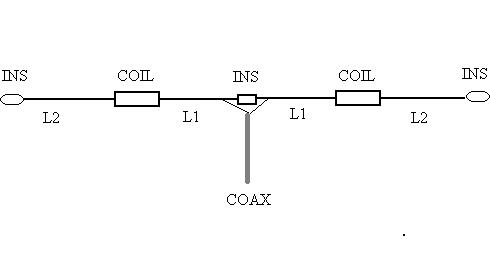
Feeding a high impedance vertical could be done by a coil and a tap for the coax, but such a coil has its own many requirements ( Q, diameter, number of turns, rain cover etc.) and may radiate by itself. This is why an easier, preferred feeder of lossless open wires is used, where current in one wire is out of phase with the current on the other, ensuring no radiation from it. A ¼ wavelength section of 300Ω Twin lead solves nicely our problem. Its far end shorted, twisted and soldered. One conductor of the Twin lead connects to the bottom of the main element by a hose clamp, while the other wire is left not connected. Keep the Twin lead away of ground at the height of the bottle insulator. The necessary impedance of that specially designed for one single band ¼ wavelength matching section, is found out by a very simple formula for matching two (very) different impedances:

Zmatch = √ Zant × Ztx

The bottom end of the Slimtenna presents estimated impedance in the vicinity of ~1500Ω, which I could not actually measure. Adding it to our formula looks like this

= √ 1500 × 50 = √ 75000 = 273.86 Ω

A good quality 300Ω Twin Lead will be near enough for that matching purpose of ours. One more thing to be done is finding the real length of that ¼ wl section. We’ll have to take into account the slowdown speed of our wave, caused by the plastic insulation covering the conductors of the Twin lead. Enter Velocity factor. For Twin lead it is about 0.73, while, for instance, for coax cable it goes down to 0.66. We'll have to multiply the ¼ wl of our matching section by that Velocity factor (0.73) which means actually shortening the way our wave has to travel. To do that we have to decide what our working frequency is – say 14,200 mHz.:

Wavelength in meters = 300 / F MHz
300 / 14.200 = 21.12 meters, but we need only the ¼ of it, so
21.12 / 4 = 5.28 meters, now times “Velocity factor”
5.28 × 0.73 = 3.85 meters of Twin lead
This is the length of the Twin lead to be used to feed our Slimtenna. Not very difficult.

Pierce the insulation of the Twin lead at a distance of ~40 inches from the cold end and connect two alligator clips attached to the feeding coax end. You will probably need to do some more piercing until you find the points of lowest SWR. As it is clear that Twin lead is after all a balanced component, attaching it to an unbalanced coax cable necessitates the use of a 1:1 BalUn, connected to the points you found, with minor moving back and forth for fine tuning. If you happen to have only a 4:1 BalUn, you can use it instead, by looking for the right connection points (~200Ω) further on along the Twin lead, closer to the antenna leg.

Last but not least – from the upper end of the coax cable make a coil of 8 turns (close wound) with a diameter of about 8", without cutting it. You can wrap it on a ~8" plastic coil form (“borrow” a cake form from your wife) or have it air wound. Fasten it in such a way that it looks like a coil and remains like that. This device will prevent the outer side of the coax braid from joining the gang, turning into an antenna by itself, while the inside stream of current is unobstructed. This phenomenon is called “Common mode currents”, meaning - currents flow on the external side of the coax braid during transmission. In common mode language it is simply an RF choke preventing your joyful SSB gurgles from appearing on your “lovely” neighbors TV, Hi Fidelity, computer, wireless phone etc. etc.

Make one last check for the lowest SWR –1.2:1 is very acceptable and you can now solder the BalUn wires to the Twin lead and cover all vulnerable joints with hot glue, RTV etc.

This 4X4 Slimtenna, if adjusted properly and operated correctly as a monoband vertical antenna, will turn out to be your “pileup-buster of the house”– try it!

My best wishes for a good luck with this fine project – 73 de Eli 4X4LH