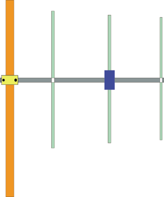
FIG.1 shows a 3 elements VHF Yagi "homebrew" antenna designed with YAGIMAX 3.
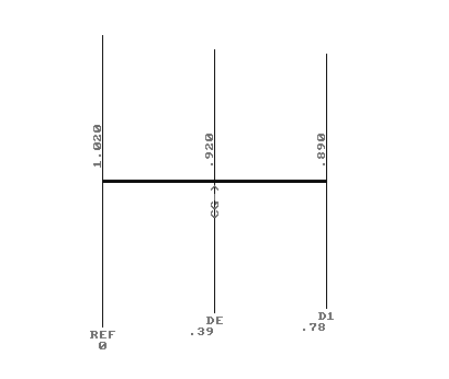
FIG.1
FIG.2 shows a table for the SWR, GAIN and F/B ratio.
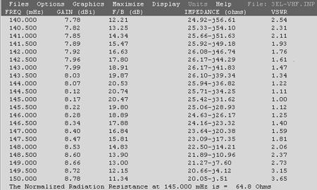
FIG. 2
The maximum forward GAIN is about 8,17 DBi (6 DBd) on 145 MHZ. With 6 DBd (6 DBd = 8,15 DBi) gain, this antenna offering an Effective Radiation Power 4 times greater of the transceiver output (without Coaxial-Loss), i.e if you have a VHF transceiver with output Power of 50 Watts, your ERP will be multiplied 4 times = 200 Watts (in the forward gain direction). The antenna is compact enough (78 cm. Boom between Reflector-director) with excellent F/B ratio ( 20 DB) .
The Impedance on center frequency (145,000 MHZ) its 65 Ohms. If you connect a 50 Ohms coaxial cable directly to dipole, the SWR is 1.3:1
In practice the antenna needs a "matching system" for a 50 Ohms coaxial cable feeder ( H-100, RG-213 or similar) in order to minimise the SWR ratio to 1:1##
I have used a "Hairpin" system (FIG. 3), which is very simple and effective "matching method". YAGIMAX antenna design program including a calculation-tool for the Hairpin's dimension, depending on "Data" of the table above (FIG.2)
The Drive Element is an "Open - Dipole" (two pieces of about "Lambda/4") with overall length 0.92 m. (see FIG.1) FIG.3 shows the Drive-element (Dipole) and the Hairpin construction on the dipole's plastic box. Keep in mind, by using a Hairpin the dipole must be a bit-shorter than normal, in order to act as a capacitive-element (25.42-j31.62 at 145 MHz). Thus the overall length of dipole is about 92 cm.The space between the two screws is 2.2 cm (dimension B) and the dimension "A" is 5 cm for 1:1 SWR (on my antenna). If you have not the optimum SWR (1:1) we can increase (or decrease) the "A" dimension a few millimetres, looking for the minimum SWR.
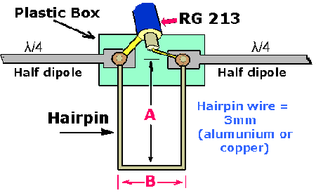
FIG. 3
The antenna is being constructed by using 15 x 15 mm aluminium boom and I have used for the elements tubular aluminium rods of 8 mm diameter. If the elements are placed directly to the boom, without a plastic piece for isolation, the dimensions must be 5mm longer (Reflector = 1025 & director = 895). The plastic box which I have used for the dipole it was from an old TV-antenna.
*NOTE: if you place the antenna with Vertical polarization, the "center-cable" of Coaxial must be connected with the upper-section of dipole and the "shield" of Coaxial with the down-part of dipole.
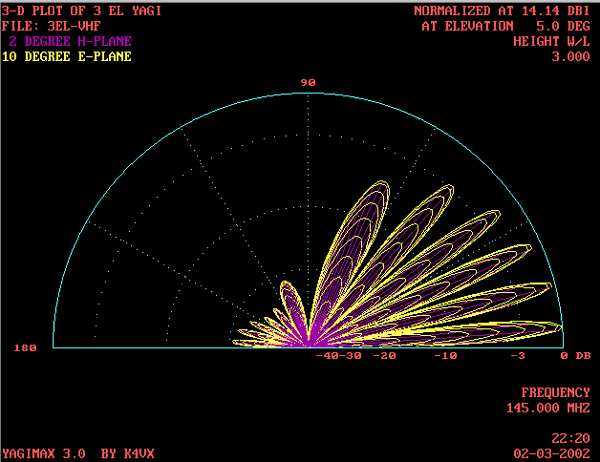
Finally, the FIG. 4, 5 shows the polar-plots of 3 Elements VHF Yagi.
*********
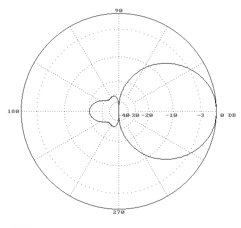
FIG.4
Can you please explain me what is this "25.42-j31.62 "
ReplyDeleteEnver Ibrovic
e77x.enver@bih.net.ba
73
Hello,
ReplyDeleteThank you for the details,but a picture of the finished antenna will be nice too. :D.
73's