Below is another end-fed antenna made from a random length of wire connected to the back of the tuner. The wire then exits the shack and goes to a high support where it then runs horizontally to another high support. The tuners groundside must be connected to a good RF ground, since a poor ground causes high losses. This antenna is commonly called a "long wire." Since the end of the antenna comes in the shack, you will be exposed to high levels of RF. In addition, this type of installation may cause RF to be picked up in the microphone, noted by distortion. The feed-point of the long wire being connected directly at the output of the tuner can have an impedance of a few ohms to a thousand ohms depending on the antennas length. If the wire is cut to a multiple of a half wave at the lowest frequency, the system will be efficient since it is fed at a voltage point and very little current flows into the ground. This antenna is really a variation of an inverted-L fed directly without a feed-line from the tuner.
Collection of Amateur Radio Antenna Projects and informations
Tuesday, February 15, 2011
End-Fed Random Length Antenna
Below is another end-fed antenna made from a random length of wire connected to the back of the tuner. The wire then exits the shack and goes to a high support where it then runs horizontally to another high support. The tuners groundside must be connected to a good RF ground, since a poor ground causes high losses. This antenna is commonly called a "long wire." Since the end of the antenna comes in the shack, you will be exposed to high levels of RF. In addition, this type of installation may cause RF to be picked up in the microphone, noted by distortion. The feed-point of the long wire being connected directly at the output of the tuner can have an impedance of a few ohms to a thousand ohms depending on the antennas length. If the wire is cut to a multiple of a half wave at the lowest frequency, the system will be efficient since it is fed at a voltage point and very little current flows into the ground. This antenna is really a variation of an inverted-L fed directly without a feed-line from the tuner.
DL2HCB Multiband Delta Loop
After a Qth change last year, I was fortunate to get permission for an outside antenna. The new antenna was built with the following considerations in mind. At least 10 - 20m coverage Open wire feed to simplify matching the various impedances Loop design, because it is less sensitive to nearby objects and it requires less real estate, considering the length of the antenna. Broadside radiation on all bands as the antenna is running N/S and I wanted most of the power into E/W direction.
While studying "Cubical Quad Antennas" by Orr/W6SAI & Cowan/W2LX, I notices the mini-X-Q (eXtended Quad) which is basically a 3/2 wave open loop with 3 db gain. Because of limited space and height 928ft), I have built the 10m mini-X-Q and modified it into a delta.
The next step was to convert it into a multiband antenna, giving comparable results to a mono-band loop or dipole. At the open end of the loop a 1/4 wave shorted stub for 28Mhz was added. The stub and the feed line is made of 450 ohm ladder line. The stub opens the loop on 28Mhz, on all other frequencies the antenna is working as a closed loop.
The antenna has been in use for a few weeks now and produced solid signals within Europe, nevertheless DX has also been worked e.g 20m with Dave FY/DJ0PJ as one of the first QSOs, 2 way QRP of course. I have also used the antenna on 30m and 40m to contact other Euopean stations.
Quads antenna
Like a Yagi antenna, a quad is directive. That is, it focuses your RF power in a particular direction. In terms of how they are put together, quads are different animals. They consist of two or more loops of wire, each supported by a bamboo or Fiberglass cross-arm assembly. The loops are a quarter wavelength per side (one full wavelength overall). One loop is driven and the other serves as a parasitic element—usually a reflector. A variation on the quad is called the delta loop. The electrical properties of both antennas are the same. Both antennas are shown in Figure 2. They differ mainly in their physical properties, one being of plumber’s delight construction, while the other uses insulating support members. One or more directors can be added to either antenna to obtain additional gain and directivity.

Figure 2—Typical quad and delta loop antenna designs. The 1/4 wavelength of 75-Ω coax acts as a matching transformer between the 100-Ω feed point impedance and the 50-Ω impedance of the station coax.
From QST August 2000
Old Receiving Magnetic Loop Antennas
by Igor Grigorov, RK3ZK
Receiving magnetic loop antennas were widely used in the professional radio communication from the beginning of the 20 Century. Since 1906 magnetic loop antennas were used for direction finding purposes needed for navigation of ships and planes. Later, from 20s, magnetic loop antennas were used for broadcasting reception. In the USSR in 20- 40 years of the 20 Century when broadcasting was gone on LW and MW, huge loop antennas were used on Reception Broadcasting Centers (see pages 93- 94 about USSRs RBC). Magnetic loop antennas worldwide were used for reception service radio stations working in VLW, LW and MW. The article writes up several designs of such old receiving loop antennas.

Old Receiving Magnetic Loop Antenna
Small loop antennas (magnetic loops)

Coupling into the loop can either be by using a small loop within the main loop, or as shown, by tapping around the loop(via an isolating transformer, to allow the loop to float relative to ground). Using the tapping method gives a more obvious idea of loop impedance, and so has been used here. Calculating the capacitance value is easy enough: C(pF) = 0.0885A(square cm)/d(spacing in cm), giving 4425pF at 7MHz and 16 594pF at 3.7MHz. Ignoring effects due to the capacitors finite length, this corresponds to reactances of 5 ohms at 7MHz, and 2.72 ohms at 3.7MHz.
Assuming a constant current around the loop, the voltage across the capacitance is 5/1.45 x that across the feedpoint, which is 50 ohms. Thus for 100W drive, V = 70.7 x 5/1.45 = 244v. This gives the following loop current:
7MHz = 244/5 = 48.8A 3.7MHz = 244/1.7 = 100A
High currents are inevitable since the loop is not only much shorter than a quarter wave monopole, but being in phase, the two verticle section (say) currents are also in opposition (the radiatedsignal being a result of the small though finite difference between path lengths).
 Return loss for loop tuned to 7MHz [-25dB at resonance]
 Return loss for loop tuned to 3.7MHz [-32dB at resonance]
From these plots, you can see the 3dB bandwidth points (ie 6dB return loss) are 120KHz for the 7MHz antenna, and 30KHz for the 3.7MHz one. For solid state transceivers that have no output match tuning, this corresponds to an un-retuned operating range of about 60KHz at 7MHz (wide enough for the entire UK ssb segment) and 15KHz or so on 3.7MHz.
Using a remote tuner, these narrower figures could be trebled without incuring too much loss, but it would be sensible to use a coupling loop, not a ferrite transformer, if this is contemplated. A coupling loop circumference of 2.2m gave a good 50 ohm match when tried.
Magnetic Loop Antenna
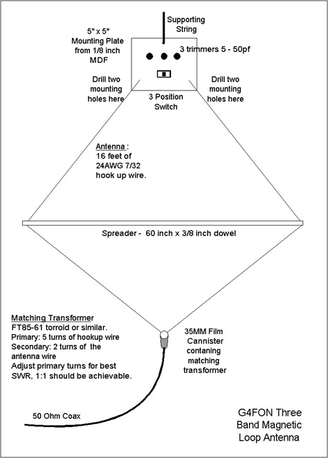
Described here is a simple multi-band magnetic loop antenna designed for 20, 30 and 40 metres, but by changing the overall length of the wire coverage of other bands is feasibleFor its size, the performance of the antenna always astounds me, although it is never going to replace a Yagi! The antenna is made from 16 feet of 24AWG 7/32 hook up wire. At the top of the antenna is a mounting plate which supports the three position band change switch and the three tuning capacitors. Each capacitor resonates the loop on one band. A piece of string is attached to the top of the mounting plate to support the antenna during operation. The matching transformer, at the bottom of the antenna, is wound on an FT50-61 torroid (this component does not seem too critical, but you may need to adjust the turns ratio, see later), which is housed in a 35mm film canister for protection. At the bottom of the film canister I have fitted a cable strain relief for the coax cable.
Construction
First mount the three position switch and the tuning capacitors on the mounting plate. At the top of the plate drill a hole for the supporting string, at the bottom of the plate drill two pair of holes in each corner to support the ends of the wire.
Measure 16 feet of hook up wire and find the midpoint by folding the wire back on itself. Pass the wire through the torroid and then pass one end through again to give two turns. Drill a hole on the opposite sides of the 35mm film canister and pass one end of the wire through each hole.
Drill a small hole about ½ inch from each end of the spreader and pass each end of the wire through one hole. Next pass the ends of the wire through the two holes in the mounting plate, making an overhand stitch pattern to act as a strain relief Put a bit of insulating tape on the antenna wire at the halfway point on each side to prevent the wire slipping through the spreader.
One end of the wire is connected to the common of the switch. Each position of the switch is connected to a single capacitor and the other side of the capacitors are commoned together and connected to the other end of the antenna wire.
Onto the ferrite torroid wind a further five turns of hook up wire and connect the ends to the coax cable.
Alignment
Aligning the antenna is straightforward, first set the switch to the first band position (20metres) and adjust the corresponding trimmer capacitor of maximum noise on receive. Move the switch to the second position and adjust the corresponding trimmer for maximum noise on 30 Metres. Repeat this for 40 metres. If you cannot obtain resonance on 40 metres, it may be necessary to add a second trimmer in parallel.
Once the antenna is roughly tuned, apply some RF through an SWR bridge and fine tune the capacitors for the lowest SWR on the QRP frequency of each band. Make sure you switch to receive while adjusting the trimmers as there are high voltages across the capacitors when on transmit.
Finally, experiment with the number of turns on the primary of the torroid to achieve the lowest SWR on all bands, switching between bands to check after each change. Changing the turns ratio may affect the resonant frequency of the loop.
If you have access to an antenna analyser, such as the MFJ range, then the job of final alignment is simplified.
What is a magnetic loop antenna?

Child and Radio 1925 Franz Fiedler (1885-1956)
I will try to explain in few words how the small magnetic loop antenna works.
1) The magnetic loop antenna is an RF transformer. The primary is the small inner loop that is 1/5 of the size of the main loop. The secondary is the main loop, and is the actual antenna. This outer conductor is closed by a variable tuning capacitor. The two loops are isolated, with no electrical contact between the inner loop and the outer loop.
2) The magnetic loop antenna is a high “Q” device, so the band width is very narrow. Even minor frequency changes will require the user to retune the antenna, but in exchange the antenna provides superior rejection of unwanted signal reception, the best receiving gain and the lowest SWR in transmit.
3) The magnetic loop antenna can be used for either vertical or horizontal polarization, and the small size makes it easy to alternate between the two.
4) In most radio activities we use the loop in the vertical position -- providing HORIZONTAL polarization -- supported by a small pole. The antenna can be turned freely in both directions to minimize or even completely eliminate man made noise coming from other directions. This position provides a "figure 8" radiation pattern similar to larger dipole antennas.
For condo windows, hotel balconies and other space-limited locations, we use the loop in the horizontal position, which (of course) gives vertical polarization and an omnidirectional radiating pattern.
5) The small magnetic loop works perfectly at low heights. A one meter diameter loop works perfectly one meter above the soil.
6) The small magnetic loop doesn’t need counterpoises, making it ideal for temporary operating locations, or for situations in which there is no room available for counterpoise wires.
A Magnetic Loop Antenna
Various articles have appeared describing magnetic loops for HF use, some with complicated methods of remote tuning and the antenna can be quite a useful and interesting project.
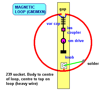
The article in Sprat 61 my Tom, GM3MXN describes a loop useable from 7 - 21 mHz, using half inch copper tube 3 feet in circumference. As shown, there is a gap at the top of the loop, which may be about 3/4 inch, either side of which is connected to the tuning capacitor, which can be about 250 pF. The inner of the SO239 socket at the base of the loop is soldered onto the centre of the loop, with the inner forming a gamma match to the tube, about 9 inches from the earthy connection. This is adjusted for minimum SWR. As show, the loop can be mounted on a wooden support and is fed with 50 ohm coax.
Notes
Tuning of the capacitor is very critical, and it may be advantageous to use more than one slow motion drive, which is what I did in my version.
It should be noted that a high potential is present across the gap, and even at QRP levels can be dangerous. Certainly with higher powers, this situation can be LETHAL. I would personally not recommend the use of such a loop in the shack because in my opinion even, QRP levels can produce what may be dangerous amounts of RF, which has been blamed for brain damage. Suffice it to say that I know of one local who did use a mag loop indoors and wondered why the paint next to the loop was bubbling (!), and another who used a handheld VHF/UHF handheld, always with the rig next to his head. He died of a brain tumour. Whether there is any medical evidence or not, I think it wise to avoid situations of RF close to the body. Is it worth the risk?
For high power use a wide spaced capacitor is needed to avoid flash over.
Maximum radiation is off the ends of the loop, not broadside on, as in a quad or delta loop.
MAGNETIC LOOP
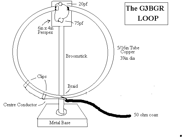
This ia a home built Magnetic loop antenna which was used by G3BGR, indoors on 7,10 and 14Mhz. The basic idea was in Radcom 1986
A 10 ft length of 5/16in copper tube gives a 39in diameter loop. The Gamma match is 12in of 1/8in wire spaced 1in from loop The ends of the loop are terminated with a 75pf variable capacitor and a 20pf variable to act as fine tuning.
No Antenna Matching Unit was necessary and a good match was obtained on the three bands.
WA1ION version of the K9AY loop
By Mark Connelly, WA1ION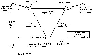
The K9AY loop antenna can provide a cardioid (heart-shaped, single-null) pattern when one end of the antenna is connected to ground through a variable DC resistance. This occurs because of the interaction between electric and magnetic field pick-up patterns.
The drawing provided above are of a K9AY loop tested at sites in Billerica, MA and East Harwich, MA during 1999.
[To get a larger version, click on the drawing above.]
Make a magnetic loop antenna for 7-21 mhz
Magnetic Loop Diagram
Magnetic Loop antenna
This antenna has several advantages, not least being only 1 metre diameter! This loop relies on being horizontally polarised and receives only the magnetic wave, thus as most noise in the domestic environment is vertically polarised and electrical wave, it delivers low noise to your transeiver/receiver, which makes for nice clean listening. In addition any signal arriving in the direction of the loop end on will be nulled out, this can be useful to get rid of an interfering signal by simply rotating the loop leaving the desired signal in the clear. It can be used indoors with ease and works well at ground level which is not the case for long wire/dipole antennas at shortwave wavelengths.
So what are its disadvantages? Well its tuning is critical, such that for a small change in frequency the antenna will need to be retuned at the loop end. This is even more important for transmitting where a high reflected wave (swr) due to not being tuned correctly will damage the output stage of your transmitter! In addition due to the very high "Q" of the loop, very high voltages can build up on the loop tuning capacitor even with low amounts of power from your transmitter. It is for this reason I recommend this loop is used with a transmitter of no more than 8 watts, any more and the ordinary broadcast tuning cap will arc over with spectacular results. Of course should you wish, a higher spec/bigger air spaced tuning cap would allow higher power output transmitters to be used. Also I consider the use of remote tuning using a fairly high geared motor and insulated coupling on the tuning cap essential. For shortwave listeners manual tuning would suffice.
In setting up the tuning of the loop, connect to a receiver and tune to 14 mhz. Now tune the loop which as it nears peak tuning will cause a whooshing sound. Stop the tuning you should now hear good strength signals in your receiver. For tuning for a transmitter, 1st use receive method then apply low power and fine tune loop tuning and tweak gamma match for lowest swr.
Magnetic loop dimension details
- Diameter of loop 1000mm
- Diameter of tube 15mm
- Width of base 780mm
- Diameter of support pipe 42mm
- Loop end spacing (for tuner) 50mm
- Height of support 1590mm
- Nylon board 210x240mm
- Nylon board 240x70mm
- Gamma match width 310mm
- Gamma/loop spacing 110mm
Construction Tips
- Use a bicycle wheel with no tyre on to help form the curves of the soft annealed copper tube
- Clean the tube with wire wool before any soldering
- Use a 100 watt soldering gun for the joints, but use a small blow torch first to get the copper at temperature to take a joint
- Force some timber with the corners planed off down the plastic plumbing pipe this will stiffen the pipe as the loop is quite weighty
- Use inverted shelf brackets to support the mounting pipe and make a wooden frame wide enough to hold up the loop
simple 2.4GHz Double Quad Antenna
The simple 2.4GHz Double Quad Antenna is a compact and easy to makehigh performance antenna offering a theoretical 14 dBi gain. As with the "circular waveguide antenna" type also on this page it offers a beam-width (in the vertical plane) not far off that required to efficiently illuminate a standard
British satellite dish of f/D ratio = .72) The optimum reflector to element
spacing requires a VSWR measurement system for a precise impedance match......
3 Elements VHF Yagi antenna
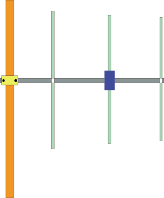
FIG.1 shows a 3 elements VHF Yagi "homebrew" antenna designed with YAGIMAX 3.
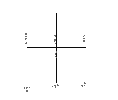
FIG.1
FIG.2 shows a table for the SWR, GAIN and F/B ratio.
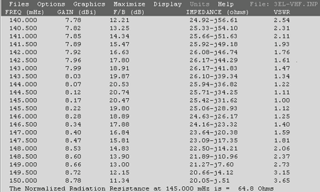
FIG. 2
The maximum forward GAIN is about 8,17 DBi (6 DBd) on 145 MHZ. With 6 DBd (6 DBd = 8,15 DBi) gain, this antenna offering an Effective Radiation Power 4 times greater of the transceiver output (without Coaxial-Loss), i.e if you have a VHF transceiver with output Power of 50 Watts, your ERP will be multiplied 4 times = 200 Watts (in the forward gain direction). The antenna is compact enough (78 cm. Boom between Reflector-director) with excellent F/B ratio ( 20 DB) .
The Impedance on center frequency (145,000 MHZ) its 65 Ohms. If you connect a 50 Ohms coaxial cable directly to dipole, the SWR is 1.3:1
In practice the antenna needs a "matching system" for a 50 Ohms coaxial cable feeder ( H-100, RG-213 or similar) in order to minimise the SWR ratio to 1:1##
I have used a "Hairpin" system (FIG. 3), which is very simple and effective "matching method". YAGIMAX antenna design program including a calculation-tool for the Hairpin's dimension, depending on "Data" of the table above (FIG.2)
The Drive Element is an "Open - Dipole" (two pieces of about "Lambda/4") with overall length 0.92 m. (see FIG.1) FIG.3 shows the Drive-element (Dipole) and the Hairpin construction on the dipole's plastic box. Keep in mind, by using a Hairpin the dipole must be a bit-shorter than normal, in order to act as a capacitive-element (25.42-j31.62 at 145 MHz). Thus the overall length of dipole is about 92 cm.The space between the two screws is 2.2 cm (dimension B) and the dimension "A" is 5 cm for 1:1 SWR (on my antenna). If you have not the optimum SWR (1:1) we can increase (or decrease) the "A" dimension a few millimetres, looking for the minimum SWR.
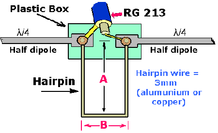
FIG. 3
The antenna is being constructed by using 15 x 15 mm aluminium boom and I have used for the elements tubular aluminium rods of 8 mm diameter. If the elements are placed directly to the boom, without a plastic piece for isolation, the dimensions must be 5mm longer (Reflector = 1025 & director = 895). The plastic box which I have used for the dipole it was from an old TV-antenna.
*NOTE: if you place the antenna with Vertical polarization, the "center-cable" of Coaxial must be connected with the upper-section of dipole and the "shield" of Coaxial with the down-part of dipole.
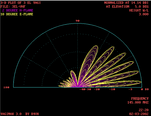
Finally, the FIG. 4, 5 shows the polar-plots of 3 Elements VHF Yagi.
*********
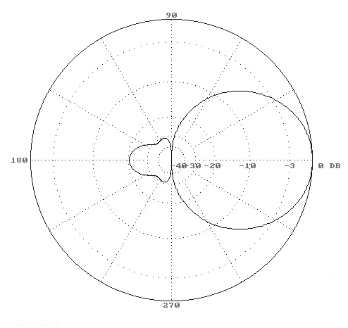
FIG.4
Slim-Jim 2m VHF Band Antenna
Submited By Nadisha 4S7NR

Slim-Jim is easy to built, no radial 145Mhz antenna. It has almost equal gain of a 5/8 lambda (Did not measure with any professional equipment, but my FT23R S-meter shows equal readings on both antennas) and much higher gain than 1/4 lambda whip. But it is much easier to buld than a 5/8 or 1/4 antenna. This looks like a modified J pole. I am sorry I don’t know who invented this, but some one who has done a good job.
To built this antenna you need 3/4 inch (even 1 inch is okay) diameter, 5 and half foot or longer PVC pipe. No 14 to 18 copper wire slightly longer than 10 feet. As shown in the picture make a hole (just enough to put the no 20 copper wire) across the PVC pipe from the one end of it. Make another one exactly 60 inches (5 feet) below the first hole (That is the bottom end of the antenna). At the bottom end you should have at least about half foot PVC left to fix it somewhere. Between two holes is Length A (see Pic).
- A = 60 inches
- B = 19 inches from the bottom
- C = 40 inches from Top
- D = 3½ inches from bottom where the coax is connected.
- G = 1 inch Gap (no connection).
-
When you connect the coax, do not connect it as shown in the picture. I draw it only to show the connection. But connect the coax up side down so the water will not go in to the coax. Center connector of the coax should connect to the opposite side of the Gap. If you want to change the matching, try to change the distance of D.
Also at the end you will have to put some tape, around the PVC from few places, so the wire will not move here and there. - Good luck!
Antenna Tuning Unit (ATU) For 27-MHz CB Radios
This antenna tuning unit (ATU) enables half-wavelength or longer wire antennas to be matched to the 50-? antenna input of 27-MHz Citizens’ Band (CB) rigs. The ATU is useful in those cases where a wire antenna is less obtrusive than a roof-mounted ‘vertical’ or ground-plane. It is also great for ‘improvised’ antennas used by active CB users on camping sites and the like because it allows a length of wire to be used as a fairly effective antenna hung between, say, a tree branch at one side and a tent post, at the other. Obviously, the wire ends then have to be isolated using, for example, short lengths of nylon wire. It is even possible to use the ATU to tune a length of barbed wire to 27 MHz. The coil in the circuit consists of 11 turns of silver-plated copper wire with a diameter of about 1 mm (SWG20).
The internal diameter of the coil is 15 mm, and it is stretched to a length of about 4 cm. The tap for the antenna cable to the CB radio is made at about 2 turns from the cold (ground) side. Two trimmer capacitors are available for tuning the ATU. The smaller one, C1, for fine tuning, and the larger one, C2, for coarse tuning. The trimmers are adjusted with the aid of an in-line SWR (standing-wave ratio) meter which most CB enthusiasts will have, or should be able to obtain on loan. Select channel 20 on the CB rig and set C1 and C3 to mid-travel. Press the PTT button and adjust C2 for the best (that is, lowest) SWR reading. Next, alternately adjust C3 and C2 until you get as close as possible to a 1:1 SWR reading.
Circuit diagram:
ATU For 27-MHz CB Radios Circuit Diagram
C1 may then be tweaked for an even better value. No need to re-adjust the ATU until another antenna is used. In case the length of the wire antenna is exactly 5.5 metres, then C3 is set to maximum capacitance. Although the ATU is designed for half-wavelength or longer antennas, it may also be used for physically shorter antennas. For example, if antenna has a physical length of only 3 metres, then the remaining 2.5 metres has to be wound on a length of PVC tubing. This creates a so-called BLC (base-loaded coil) electrically shortened antenna. In practice, the added coil can be made somewhat shorter than the theoretical value, so the actual length is best determined by trial and error. Finally, the ATU has to be built in an all-metal case to prevent unwanted radiation. The trimmers are than accessed through small holes. The connection to the CB radio is best made using an SO239 (‘UHF’) or BNC style socket on the ATU box and a short 50-W coax cable with matching plugs.
Active Short-Wave Antenna
The circuit presented here illustrates the fact that in spite of all kinds of new component and technology, it is still possible to design useful, and interesting, circuits. The circuit is based on two well-established transistors, a Type BF256C and a BF494. In conjunction with the requisite resistors and capacitors, these form a well-working antenna amplifier. Note that they are direct coupled. Transistor T1 is the input amplifier cum buffer, while the BF494, in a common-ground configuration, provides the necessary amplification. The amplifier is designed for operation at frequencies between 10 MHz and 30 MHz, which is the larger part of the short-wave range, and has a gain of 20 dB.
Circuit diagram:
Active Short-Wave Antenna Circuit Diagram
Inductor L1 is wound on an Amidon core Type T-37-6. The primary consists of 2 turns, and the secondary of 12 turns 0.3 mm dia. enameled copper wire. The number of turns may be experimented with for other frequency ranges. The input circuit is tuned to the wanted station with capacitor C1. The response of the tuned circuit is fairly broad, so that correct tuning is easy. The circuit is powered by a well-decoupled mains supply converter that has an output of 9–12 V. The circuit draws a current of about 5mA
Shortwave antenna ideas
The type of antenna you’ll want to use for your shortwave receiver depends on the degree of interest you have in shortwave listening, on whether you are limited to an indoor or balcony antenna. If you cannot use an outdoor antenna, you can make yourself a whip antenna from telescoping radio antenna from your local Radio Shack store. A better antenna would be to throw a 10 to 20 foot piece of insulated wire out the window, secured to a pole or tree away from your window.
You could also place a length of wire in your attic to act as an antenna. An even better antenna would be a dipole antenna “cut” for the desired radio band of most interest. In order to construct your own dipole antenna, you can refer to the diagram depicted in Figure 8-5. Simply use the formula: 468 divided by the frequency in Megahertz for example. If you wanted to construct a dipole for 7.410 MHz, you would divide 468 by 7.410. The results would be 63.157 feet, so one-half of that number is 31.5 feet. Each leg of the dipole antenna
would then be 31.5 feet. If you do construct your own dipole antenna, you should keep the antenna away from metal objects and use insulated wire and be sure to keep away from all power lines. The lead-in wire for your dipole antenna to your new receiver can be a length of RG8X min-coaxial cable.
Active antenna 1 to 20dB, 1-30 MHz range.
by
Rodney A. Kreuter Tony van Roon
"When fate or nasty neighbors prevent you from stringing a long-wire receiving antenna, you'll find that this pocket-size antenna will give the same, or even better, reception. This "Active Antenna" is cheap to build" and has a range of 1 to 30Mhz at between 14 and 20dB gain."
For conventional all-frequency short-wave reception, the general rule is "the longer the antennal the stronger the received signal." Unfortunately, between nasty neighbors, restrictive housing rules, and real-estate plots not much larger than a postage stamp, short-wave antennae often turn out to be a few feet of wire thrown out of the window--rather than the 130 feet of long-wire antennal we would really like to string between two 50-foot towers.Fortunately, there is a convenient alternative to the long-wire antenna, and that's an active antenna; which basically consists of a very short antenna and a high-gain amplifier. My own unit has been in operation successfully for almost a decade. It works satisfactory.
The concept of a active antenna is fairly simple. Since the antenna is physically small, it doesn't intercept as much energy as a larger antenna, so we simply use a built-in RF amplifier to make up for the apparent signal "loss." Also, the amplifier provides impedance matching, because most receivers are designed to work with a 50-ohm antenna.
Active antennas can be built for any frequency range, but they are more commonly used from VLF (10KHz or so) to about 30MHz. The reason for that is because full-size antennas for those frequencies are often much too long for the available space. At higher frequencies, it is quite easy to design a relatively small high-gain antenna.The active antenna shown below (Fig. 1), provides 14-20dB gain at the popular short-wave and radio-amateur frequencies of 1-30MHz. As you would expect, the lower the frequency the greater the gain. A gain of 20dB is typical from 1-18 MHz, decreasing to 14dB at 30MHz.
Circuit Design:
Because antennas that are much shorter than 1/4 wavelength present a very small and highly reactive impedance that is dependent on the received frequency, no attempt was made to match the antenna's impedance--it would prove too difficult and frustrating to match impedances over a decade of frequency coverage. Instead, the input stage (Q1) is an JFET source-follower, whose high-impedance input successfully bridges the antenna's characteristics at any frequency. Although many different types of JFET's may be used--such as the MPF102, NTE451, or the 2N4416--bear in mind that the overall high-frequency response is set by the characteristics of the JFET amplifier.
Transistor Q2 is used as an emitter-follower to provide a high-impedance load for Q1, but more importantly, it provides a low drive impedance for common-emitter amplifier Q3, which provides all of the amplifier's voltage gain. The most important parameter of Q3 is fT, the high-frequency cut-off, which should be in the range of 200-400 MHz. A 2N3904, or a 2N2222 works well for Q3.
The most important of Q3's circuit parameters is the voltage drop across R8: The greater the drop, the greater the gain. However, the passband decreases as Q3's gain is increase.
Transistor Q4 transform Q3's relatively moderate output impedance into a low impedance, thereby providing sufficient drive for a receiver's 50-ohm antenna-input impedance.


