Tuesday, June 17, 2014

Single 5/8 Flower Pot Antenna


The Single 5/8 version of the Flower Pot simply substitutes a 5/8 wave-length section for the top quarter wave of the basic half wave antenna design. The arrangement is shown in the sketch below. The 5/8λ radiator uses a 0.2λ (shorted) co-ax phasing stub to resonate the 5/8λ element. In a conventional 5/8λ mobile whip, an inductor is used to bring the 5/8λ element to resonance; however, in this Flower Pot style of antenna, using a co-ax phasing (or delay) stub suits the construction technique and has the advantage of being able to be precisely determined and cut at the construction stage.

The antenna configuration is similar to, but slightly shorter than, the “Gain Sleeve” antenna described in the RSGB Hand-book (6th Edition – figure 13.99, which itself is derived from the reactance – or shunt – fed 5/8λ monopole antenna at figure 13.84 of the handbook).
The Gain Sleeve antenna achieves an effective radiating element length of one wavelength and, since the aperture is twice that of a half wave dipole, a theoretical gain of 3dBd (gain over a dipole) could be achieved.

However, note that the Handbook indicates that in practice, the Gain Sleeve antenna would realise about 2.5dBd. The effective radiating element length of the Single 5/8 Flower Pot is 7/8λ suggesting it would have somewhat less than 2.5dBd gain.

2m Construction

2m Single 5/8 Flower Pot

Simple 1/4 Wave Ground Plane Antenna


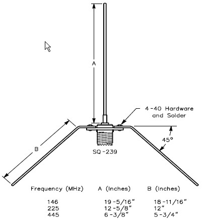
If you are just starting out or have the desire to build an antenna here is a simple and fun project. This antenna is perfect for those hams living in the primary coverage area of the .075 repeater. The radials can be made of no. 12 copper wire. The vertical radial (A) should be soldered to the center connector of the SO239. The four base radials (B & C) and (D & E) can be soldered or bolted to the SO239 mounting holes using 4-40 hardware. The four base radials then should be bend downward to a 45 degree angle. The antenna can be mounted by clamping the PL259 to a mast or even passing the coax through a 3/4 ID PVC pipe and compression clamping the PL259. Either way let your creativity flow. If you plan on mounting it outside experience teaches to apply RTV or sealant around the center pin to keep water out of the coax.

Make each radial a 1/4 wave of your desired frequency. Sometimes it helps to add a little extra length to the radials. This will give you some snipping room when you adjust the SWR.
example calculation:
Freq (mhz)    A (inches)    B&C/D&E (inches)
146 mhz            19-5/16            20-3/16

VHF/UHF Ground Plane antennas for under $20


The entire antenna consists of a panel mount SO-239, some stiff wire (like aluminum welding wire, brazing rod, 12 GA bare copper wire, electric fence wire, etc) or thin brass tubing, some solder, and four 4-40 3/8" long screws, washers, and nuts

Cut the wires to length in accordance with the chart provided for the band you want. You will end up with 5 pieces of wire, 4 the same length (radials) and one slightly longer (driven element). Use a good high wattage soldering iron to tin one end of the driven element

HINT:Cut your radials extra long, mount them on the SO-239, mark the point to start the bend, remove the radials, make the 45deg bend, remount them, then measure and trim to length. When tuning for lowest SWR, remember that the angle of the radials affects the value, so feel free to adjust them anywhere between 30 and 45 deg for best reading. Also, if tubing is used, one end of each radial can be soldered to a ring terminal or hammered flat and drilled


There are several ways to attach the radials:

  • Bend the wire through the corner hole and solder in place — Requires a lot of heat, no longer removable for transport but better electrical connection
  • Use a pair of needle nose pliers to fashion one end into a tight loop just big enough for the 4-40 screws to get through — Takes a little work, can loosen over time [use split washers for extra tension], but no soldering
  • Solder (or crimp) ring terminals on one end — clean, professional looking, but may break over time with repeat bending
Notice that the length of the radials is measured from the 45 deg bend to the tip, so which ever way you choose, allow for this extra length in your calculations.


Thursday, January 16, 2014

Homebrewed Off-Center Fed Dipole


Ocfd.jpg
Building A Homebrewed Off-Center Fed Dipole Scanner Antenna.

Aluminum/copper tubing construction:

You will need to check the fit of the tubing with the T connector and the caps while you are at the store. One combination that fits nicely is 3/4" copper pipe with 3/4" CPVC fittings (not to be confused with 3/4" PVC fittings which will be too large). The tubing/connector is held in place with 2 stainless steel sheet metal screws for connecting the balun to each element.
Find a "U" bolt to fit your mast. Drill two holes in the support pipe to fit the U bolt.The support pipe is 18" from the "T" to the mast.

Remember, bandwidth increases as diameter of the elements increases. I think, if I remember correctly, at the hardware store, that a few CPVC fittings will fit copper tubing perfectly!

Some say that the 18" element on top mounted works best,Some like the 48" element on top.It does'nt matter,it works the same. If you use the copper tubing,be sure to paint it with some good,non-conductive paint.I used to paint mine light grey. -Have fun! (Teraycoda)

For an alternate/temporary mounting option, drill a hole in one of the end caps and put in an eye bolt with a nut on the underside of the cap to secure. Be sure to secure this end cap to the copper tubing somehow, perhaps with an additional small stainless sheet metal screw. Be sure that the eye bolt itself doesn't make electrical contact with the tubing. Also, drill a small weep hole in the bottom end cap to allow any moisture to escape that may accumulate inside. Use the eye bolt and some rope to pulley the antenna up high in a tree, or use a hook to hang it somewhere. Give careful consideration to safety and grounding depending on your particular usage scenario. (Qdude)

Variation for Off-Center Fed Dipole Using Simple Wire and 75 to 300 ohm TV Balun Transformer

Offset dipole scanner antenna.jpg
Electrically, this version is the same as the one using copper tubing (above) but can be assembled quickly and is quite portable. While not as broadbanded as an OCFD using copper tubing or other metal with a larger diameter, the OCFD made from simple wire turns in great receive performance in all the commonly scanned bands, as reported here on RR in multiple message threads.
 
The legs/ends of the dipole are simple bell wire and shown here coiled up. Uncoil them and hang them vertically; doesn't matter if the long or short leg is at the top... works the same either way. The wire terminal lugs shown at the end of the legs of the dipole antenna should NOT be connected electrically to the wires - just crimp them on over the wire insulation. They are used as convenient hangers for the antenna, and not meant for electrical connection. Obviously, the lugs at the TV transformer/balun ends of the wire should be stripped before crimping on the terminal lugs to ensure contact with the antenna wires when you attach the TV transformer. Ensure the 75 ohm coax feedline that you connect from the balun/transformer runs away from the antenna at as near a 90 degree angle as possible.